Liquid crystal display apparatus having wide transparent electrode and stripe electrodes

a transparent electrode, liquid crystal display technology, applied in non-linear optics, instruments, optics, etc., can solve problems such as irregular display or after, reduced contrast of contrast, and brightness reverse, and achieve no disclination

Inactive Publication Date: 2007-03-13
SHARP KK
View PDF32 Cites 23 Cited by
  • Summary
  • Abstract
  • Description
  • Claims
  • Application Information

AI Technical Summary

Benefits of technology

[0011]In the configuration described above, an electric field is formed between one of the stripe electrodes and the wide transparent electrode. This electric field is an oblique electric field running from each stripe electrode toward the wide transparent electrode in oblique directions. Thus, the liquid crystal molecules are aligned in the direction perpendicular to the substrate surface when no voltage is applied thereto, and are aligned in the direction parallel to the oblique electric field upon application of a voltage thereto. In this way, almost all the liquid crystal molecules are smoothly aligned along the electric field and, therefore, no disclination occurs.

Problems solved by technology

The TN-type liquid crystal display apparatus, however, harbors the problem that the contrast thereof is reduced or the brightness is reversed when the screen thereof is viewed obliquely.
The liquid crystal molecules located intermediate between the first electrode and the second electrode, however, are affected by the liquid crystal molecules aligned upward to the left and the liquid crystal molecules aligned upward to the right, and cannot be smoothly aligned in the direction parallel to the substrate surface.
This unstable alignment causes disclination.
The disclination appears or disappears depending on the voltage or on disturbances, and poses the problem of causing an irregular display or an after image.

Method used


Image

  • Liquid crystal display apparatus having wide transparent electrode and stripe electrodes
  • Liquid crystal display apparatus having wide transparent electrode and stripe electrodes
  • Liquid crystal display apparatus having wide transparent electrode and stripe electrodes

Examples


first embodiment

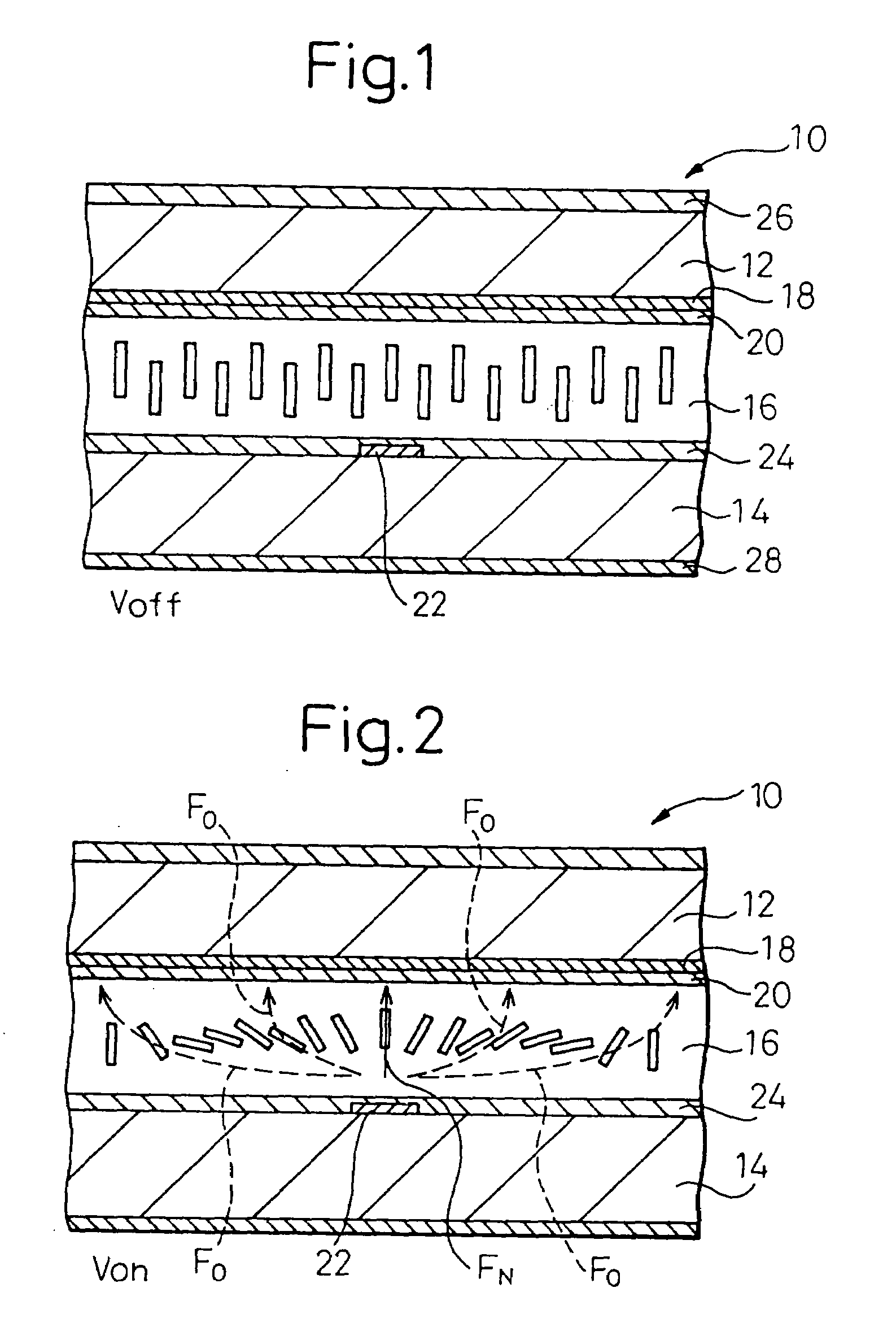
[0189]FIG. 1 is a sectional view showing a liquid crystal display apparatus 10 according to the invention when no voltage is supplied, and FIG. 2 is a sectional view of the liquid crystal display apparatus of FIG. 1 when a voltage is supplied.

[0190]In FIGS. 1 and 2, the liquid crystal display apparatus 10 according to this invention comprises first and second opposed transparent glass substrates 12, 14, and a liquid crystal layer 16 arranged between the first and second substrates 12, 14. The first substrate 12 is a color filter substrate including a color filter (not shown), and the second substrate 14 is a TFT substrate including TFTs. The liquid crystal panel is formed of a pair of the substrates 12, 14 and the liquid crystal layer 16.

[0191]The first substrate 12 includes a wide or solid transparent electrode 18 formed to cover substantially the whole surface of the first substrate 12 and a vertical alignment layer 20. The second substrate 14 includes a plurality of stripe electr...

second embodiment

[0197]FIG. 6 is a sectional view showing the liquid crystal display apparatus when no voltage is applied. FIG. 7 is a sectional view showing the liquid crystal display apparatus 10 of FIG. 6 when a voltage is applied. The liquid crystal display apparatus 10, like the embodiment of FIGS. 1 and 2, comprises first and second transparent glass substrates 12, 14 in opposed relation to each other, a liquid crystal layer 16 arranged between the first and second substrates 12, 14 and polarizers 26, 28.

[0198]The first substrate 12 includes a wide or solid transparent electrode 18 to cover substantially the whole surface of the first substrate 12 and a vertical alignment layer 20. The second substrate 14 includes a plurality of alternately extending parallel first and second groups of stripe electrodes 22a, 22b and a vertical alignment layer 24. The first and second groups of the stripe electrodes 22a, 22b are supplied with different voltages. In this embodiment, the first group of the strip...

third embodiment

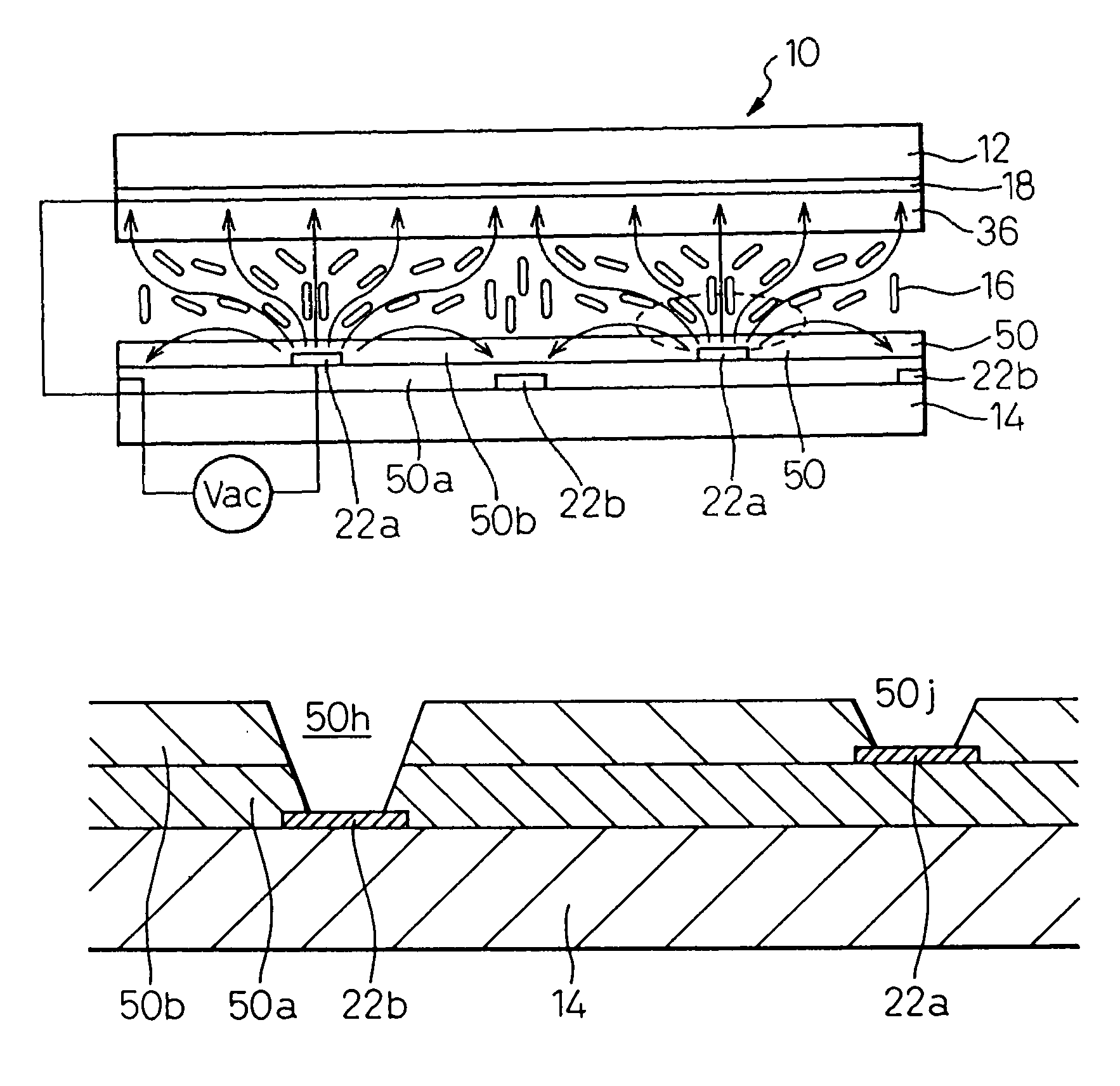
[0239]FIG. 32 is a sectional view showing a liquid crystal display apparatus according to the present invention. The liquid crystal display apparatus 10 includes first and second glass substrates 12, 14 in opposed relation to each other, and a liquid crystal layer 16 arranged between the substrates 12, 14. The first glass substrate 12 is a color filter substrate, and the second substrate 14 is a TFT substrate. The first glass substrate 12 includes a transparent electrode 18 having an entirely solid surface, a dielectric layer 36 and a vertical alignment layer 20. The second glass substrate 14 includes first and second groups of stripe electrodes 22a, 22b extending in parallel to each other, an insulating layer 50 and a vertical alignment film 24. Polarizers 26, 28, though not shown, can be arranged, as shown in FIGS. 1 and 6. Incidentally, the embodiments described below are applicable to the liquid crystal display apparatus utilizing only the horizontal electric field shown in FIGS...


PUM

PropertyMeasurementUnit
volume resistivityaaaaaaaaaa

Abstract

A liquid crystal display apparatus including pair of substrates; a liquid crystal arranged between the pair of substrates; a plurality of stripe electrodes per pixel and an alignment layer formed in one of the substrates; a transparent electrode covering substantially the whole surface of the other substrate and an alignment layer formed in the other substrate; and an insulating layer arranged in one substrate to cover the stripe electrodes. The insulating layer preferably has openings above the stripe electrodes and the openings preferably have tapered side walls.

Description

[0001]This is a divisional of application Ser. No. 09 / 454,578, filed Dec. 7, 1999 now U.S. Pat. No. 6,642,984.BACKGROUND OF THE INVENTION[0002]1. Field of the Invention[0003]The present invention relates to a liquid crystal display apparatus utilizing an oblique electric field.[0004]2. Description of the Related Art[0005]A TN-type liquid crystal display apparatus is widely used, for example, as a display unit of a personal computer. The TN-type liquid crystal display apparatus, however, harbors the problem that the contrast thereof is reduced or the brightness is reversed when the screen thereof is viewed obliquely. Thus, there is a high demand for a liquid crystal display apparatus in which the contrast is not reduced when it is viewed obliquely.[0006]Japanese Unexamined Patent Publications No. 10-153782 and No. 10-186351, for example, disclose a liquid crystal display apparatus of an IPS (in-plane switching) type in which the contrast thereof is not reduced when it is viewed obliq...

Claims


Application Information

Patent Timeline
Patent Type & Authority Patents(United States)
IPC IPC(8): G02F1/1343G02F1/1337G02F1/1333G02F1/139
CPCG02F1/133707G02F1/1393G02F1/134336
Inventor YOSHIDA, HIDEFUMITASAKA, YASUTOSHISASABAYASHI, TAKASHINAKANISHI, YOHEINAKAMURA, KIMIAKIKOIKE, YOSHIOFUJIKAWA, TETSUYA
Owner SHARP KK
Why Eureka
Try Eureka