Electrode assembly and method for manufacturing the same

Active Publication Date: 2019-01-24
LG ENERGY SOLUTION LTD
View PDF10 Cites 0 Cited by
  • Summary
  • Abstract
  • Description
  • Claims
  • Application Information

AI Technical Summary

Benefits of technology

The present invention relates to a battery design that maintains an even alignment of electrodes and separators, resulting in a constant movement route for electrons, improved cycle properties, and maximized charging efficiency. Additionally, the invention prevents wrinkling and size increase of the battery due to the negative electrode tab.

Problems solved by technology

However, a method for manufacturing the electrode assembly has a problem in which it is difficult to align electrode tabs in case of a multi-tab including a plurality of tabs because terminals (the electrode tabs) are attached to non-coating portions of a positive electrode plate and a negative electrode plate, which are wound.
Also, if the electrode tabs are not constantly aligned, an electron movement route may be changed to cause kinetic balance that is one of causes of cycle degeneration.

Method used


Image

  • Electrode assembly and method for manufacturing the same
  • Electrode assembly and method for manufacturing the same
  • Electrode assembly and method for manufacturing the same

Examples


embodiment 1

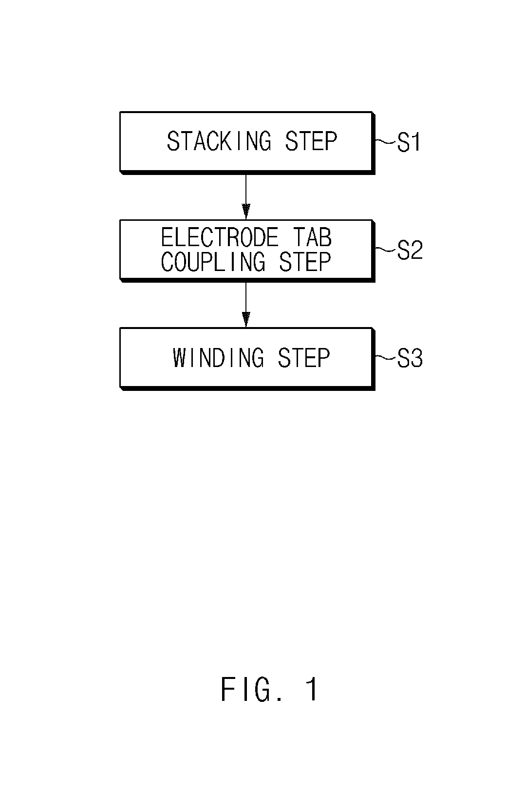
[0053]FIG. 1 is a flowchart illustrating a method for manufacturing an electrode assembly of the present invention.

[0054]As illustrated in FIG. 1, a method for manufacturing an electrode assembly according to Embodiment 1 of the present invention includes a stacking step (S1), an electrode tab coupling step (S2), and a winding step (S3).

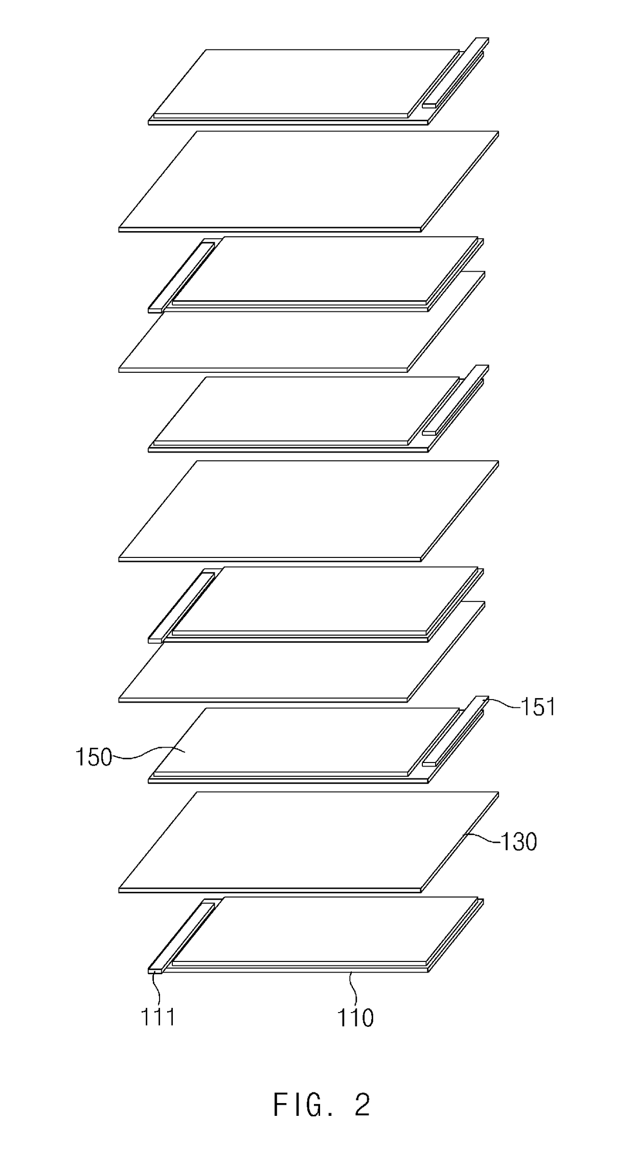
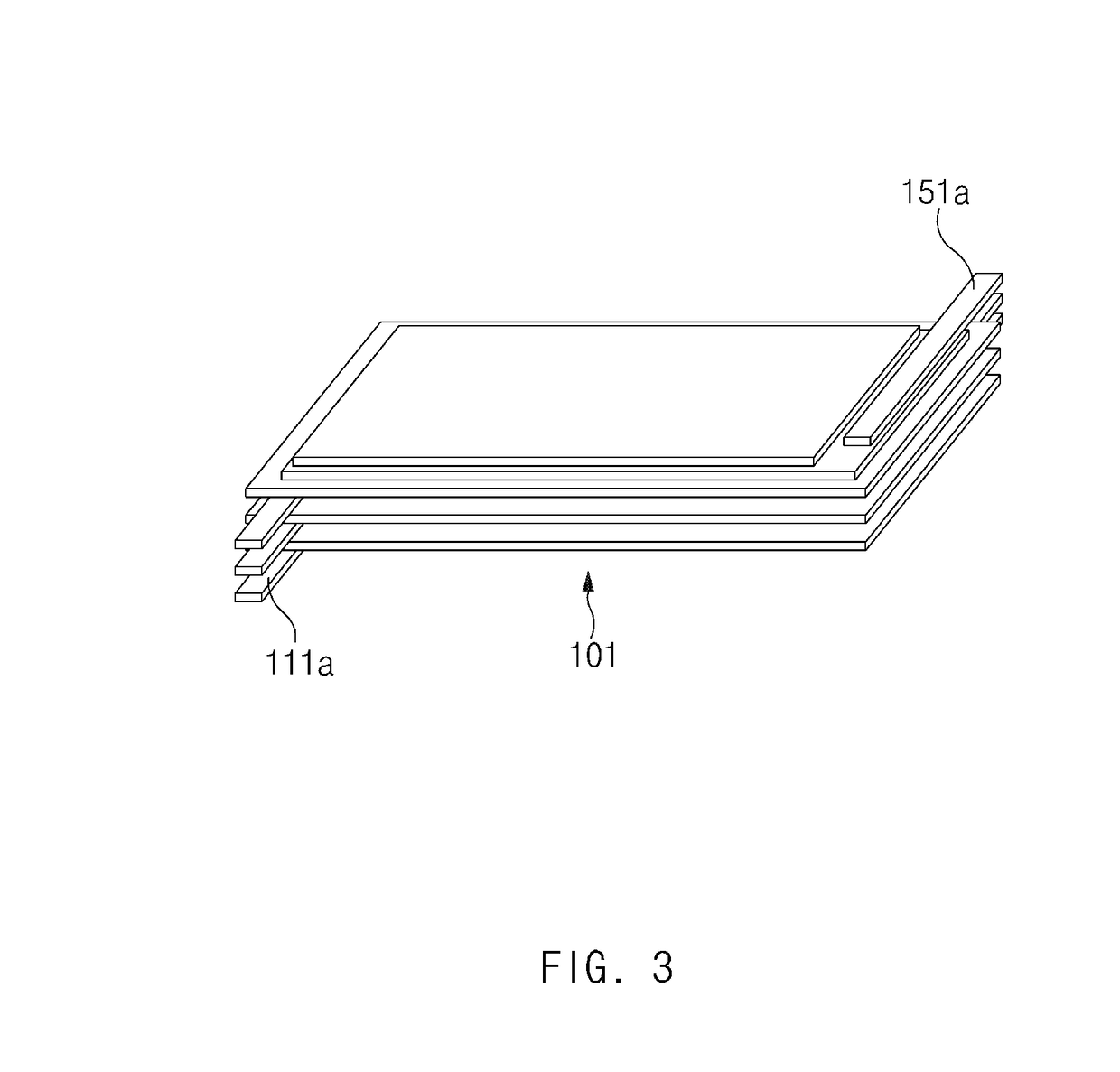
[0055]FIG. 2 is an exploded perspective view of the electrode assembly according to Embodiment 1 of the present invention, and FIG. 3 is a perspective view illustrating a stacked state of the electrode assembly of FIG. 2.

[0056]As illustrated in FIGS. 2 and 3, the stacking step (S1) according to Embodiment 1 of the present invention is a step of forming an electrode stack 101 by repeatedly stacking each of a plurality of negative electrodes 110, each of a plurality of separators 130, and each of a plurality of positive electrodes 150 so that the separator 130 is stacked between the negative electrode 110 including an electrode tab and the positive el...

embodiment 2

[0075]FIG. 6 is a bottom view of a negative electrode tab bundle of the present invention.

[0076]As illustrated in FIG. 6, in a stacking step (S1) according to Embodiment 2 of the present invention, a plurality of negative electrodes, a plurality of separators, and a plurality of positive electrodes may be stacked. Here, electrode tabs 111 formed on the plurality of negative electrodes may be stacked on each other, and positive electrode tabs 151 formed on the plurality of positive electrodes may be stacked on each other.

[0077]Also, in an electrode tab coupling step (S2) according to Embodiment 2 of the present invention, the stacked positive electrode tabs 151 may be coupled to each other through welding, and the stacked negative electrode tabs 111 may not be coupled to each other.

[0078]In a winding step (S3) according to Embodiment 2 of the present invention, an electrode stack 101 may be wound in the state in which the positive electrode tabs 151 are coupled to each other through...

embodiment 3

[0082]FIG. 7 is an exploded perspective view of an electrode assembly of the present invention, FIG. 8 is a perspective view illustrating a stacked state of the electrode assembly of FIG. 7, and FIG. 9 is a front view illustrating a wound state of the electrode assembly of FIG. 8.

[0083]As illustrated in FIGS. 7 to 9, in a stacking step (S1) of a method for manufacturing an electrode assembly according to Embodiment 3 of the present invention, positive electrode tabs 151 of a plurality of positive electrodes are disposed on the same vertical line V and stacked on each other, and negative electrode tabs 111 of a plurality of negative electrodes are formed to be gradually close to the positive electrode tabs in a stacked direction of the negative electrodes.

[0084]Here, the negative electrode tabs 111 may be disposed to overlap each other on the same vertical line H after being wound in the winding step (S3) (see FIG. 9).

[0085]In an electrode tab coupling step (S2), the positive electr...


PUM


Abstract

The present invention relates to an electrode assembly including a multi-tab in which tabs are capable of being aligned and a method for manufacturing the same.The method for manufacturing an electrode assembly according to the present invention includes a stacking step of repeatedly stacking a negative electrode, a separator, and a positive electrode so that the separator is stacked between the negative electrode including an electrode tab and the positive electrode including an electrode tab to form an electrode stack, an electrode tab coupling step of coupling the electrode tabs having at least two or more same polarities of the electrode tabs of the electrode stack to each other, and a winding step of winding the electrode stack.

Description

CROSS-REFERENCE TO RELATED APPLICATION[0001]The present application claims the benefit of the priority of Korean Patent Application Nos. 10-2016-0145420, filed on Nov. 2, 2016, and 10-2017-0145158, filed on Nov. 2, 2017, which are hereby incorporated by reference in their entirety.TECHNICAL FIELD[0002]The present invention relates to an electrode assembly and a method for manufacturing the same, and more particularly, to an electrode assembly including a multi-tab in which tabs are capable of being aligned and a method for manufacturing the same.BACKGROUND ART[0003]Lithium secondary batteries may be divided into lithium metal batteries, lithium ion batteries, and lithium secondary batteries according to a shape of an electrolyte.[0004]Here, such a lithium secondary battery may not require a firm metal exterior and be manufactured in various sizes and shapes according to a use thereof. For example, the lithium secondary battery may have a thickness of 3 mm or less and a weight that i...

Claims


Application Information

Patent Timeline
IPC IPC(8): H01M10/0587H01M10/0525H01M2/26H01M50/538
CPCH01M10/0587H01M10/0525H01M2/266H01M10/0431Y02E60/10H01M50/538Y02P70/50H01M50/531H01M50/54H01M50/46
Inventor KIM, SU HYUNKIM, JI HYUN
Owner LG ENERGY SOLUTION LTD
Why Eureka
Try Eureka