Propeller assembly

a propeller and assembly technology, applied in watercraft propulsion, marine propulsion, vessel construction, etc., can solve the problems of long time to get up, difficult to pull out to the deeper end, and poor hole shot, etc., to increase the thrust and power of the boat, reduce or eliminate the problem, and easy and inexpensive methods to increase the power of the boat motor

Active Publication Date: 2019-12-03
HOLESHOT PERFORMANCE PROPELLERS LLC
View PDF20 Cites 0 Cited by
  • Summary
  • Abstract
  • Description
  • Claims
  • Application Information

AI Technical Summary

Benefits of technology

[0028]Disclosed herein is an easy and inexpensive method to increase power to a boat motor. While the problem to be solved was avoiding hole shot issues for boats in shallow water, the present invention has numerous benefits beyond the remedy for hole shot concerns. Further disclosed is an auxiliary propeller allowing the combining of two propellers in place on any given engine. This is not suitable for counter-rotating systems, but otherwise useful or suitable for all single output shafts. Still further disclosed is a unique coupling system to attach two propellers together without the need for a method of adhesively securing. Herein, adhesively securing is defined as welding, a chemical adhesive suitable for metal or plastic, or screws to hold the propellers in place or the like. Assembly of the dual propellers can be achieved manually or automatively (or by machine). The dual propeller system increases the thrust, and power of the boat. A perfect alignment is formed when the two propellers are combined, minimizing or eliminating the problems caused by welding or securing propellers with screws (problems such as pull of the metal, vibrations weakening the weld or attachment). A barrel or coupling device having a crown (grooves) was developed which fits securely in the interior section of the lead propeller, and allows for the combining of two propellers onto one engine. It was found that the present inventive device was able to move a boat out of shallow water using about half the RPMS (rotations per minute) than would normally be used. For exemplary purposes, most hulls require less than 2500-3000 RPMS to get on plane in shallow water conditions (shallow water defined herein as about 0″-12″ of water, or preferably anything less than 6″) with this device; with existing propeller systems it would require wide open throttle to get out of the hole.
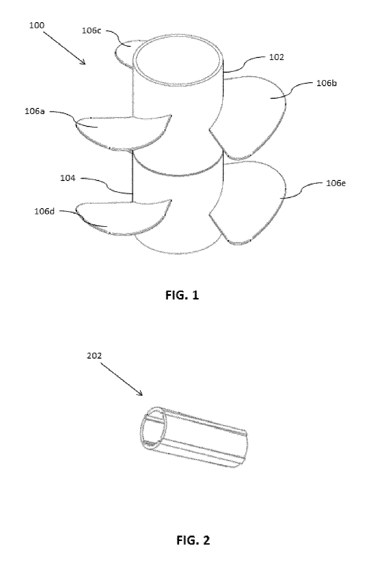
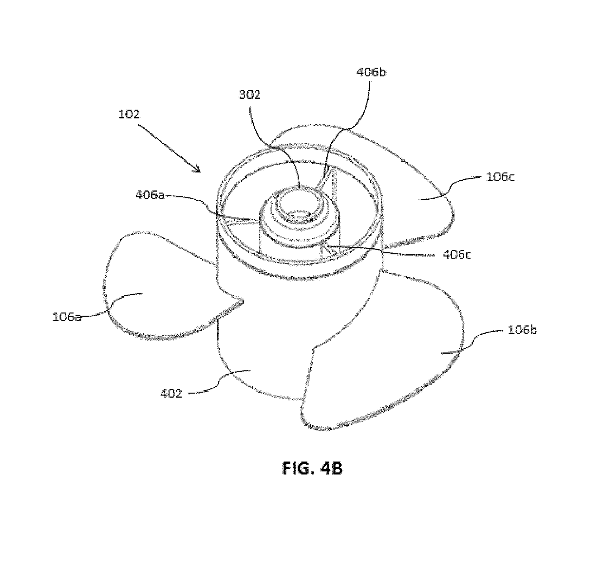
[0029]An object of the present invention is to provide a method to enhance the power and thrust of an watercraft engine by combining two propellers; one becomes the trailing propeller that is secured and aligned coaxially with an existing or lead propeller. Broadly, the dual propeller assembly comprises a leading propeller and a trailing propeller, wherein the leading propeller comprises a cylindrical hub having an extended shaft portion on one end; mounting ring attached to the opposite end of the cylindrical hub which accepts a locking nut; the trailing propeller comprises a cylindrical hub and having a drive sleeve engaged with a propeller shaft wherein the propeller shaft secures the leading propeller and the trailing propeller with the locking nut.
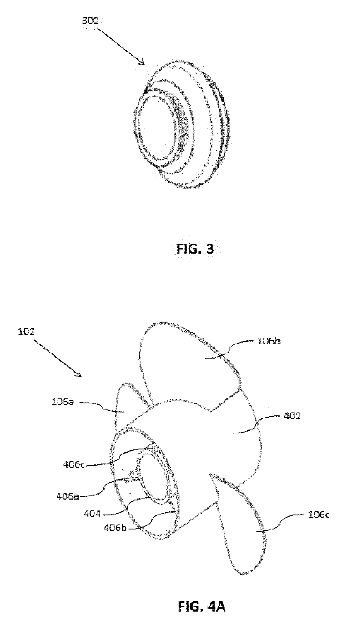
[0031]In an embodiment, the trailing propeller includes a first cylindrical hub (or barrel with grooves at its end, also referred to as a coupling system), a second cylindrical hub (accepting the barrel with grooves), and a conical profile there between. The first cylindrical hub or barrel includes a plurality of grooves on one end that are described and shown herein as rectangular in shape. While rectangular is a preferred shape, other shapes such as semi-circular, square-like, round over, V-groove, etc. are acceptable provided the grooves fit into the propeller assembly, or mate together. The shape allows the figure sliding over the lead propeller. The grooves are to be aligned with preferably 30° increments for timing purposes and are equidistant to each other. The second cylindrical hub includes a cylindrical mount ring that holds a drive sleeve. The cylindrical mount ring is attached to the second cylindrical hub or spline by using a set of radial mount ring flanges. The conical profile formed between the first cylindrical hub or barrel, and the second cylindrical hub allows smooth alignment of the trailing propeller with most if not all of current or existing propellers. The first cylindrical hub having the barrel with grooves is inserted in a hub (or interior portion) of the existing propeller. The outer diameter of the barrel is selected based on the inner diameter of the hub of the existing propeller. The trailing propeller can be effectively and consistently used with propellers made by any existing manufacturer.
[0032]The present invention comprises, in one embodiment, a barrel having grooves on one end, and ancillary parts to secure the propellers, all of which form an aligning system. The barrel fits into what becomes the trailing propeller which is coupled and aligned to a leading propeller without adhesively securing or welding. The leading propeller is any existing propeller. Thus, the coupling of the trailing propeller with the leading propeller is not time-consuming and less labor-intensive to combine than existing welding or attaching techniques. The absence of welding eliminates a potential misalignment of the trailing propeller and the leading propeller. Further, the trailing propeller may be attached to an engine irrespective of the engine manufacturer. Moreover, the trailing propeller and leading propeller do not counter-rotate with each other.
[0033]An alternate embodiment shown in FIG. 15, involves placing porting holes (1502) in the leading propeller to exhaust vapors and improve vapor displacement. At idle speeds, while the boat is in deep water, the vapor (porting) holes have been found to improve exhaust of the gas vapors. The holes create a turbulence which allow hole shot to increase under these conditions. Without the holes, the boat had a weaker hole shot in deep water (defined as greater than twelve inches).

Problems solved by technology

Typically, once the boat is in shallow water, it will have difficulties pulling out to the deeper end.
A poor hole shot would often be caused by the motor laboring and taking a long time to get up to speed (often because not properly propped for the load, or the boat is underpowered).
As an example, a high powered boat may have excellent top speed, but a poor hole shot, i.e., as the boat begins to move, the boats' hole continues to move and even perhaps increase in depth due to the changing angle of the boat.
A lower pitched propeller, which may help in removing the boat from a hole shot, has the disadvantage of generally having a lower top speed motor (defined herein as the engine and propeller).
This is because the lower pitched propeller cannot navigate (or screw) itself though the water, as easily as a higher pitched propeller.
Hole shot-related problems often occur during take-off of a boat, and most often in shallow versus deep water.
Existing motors having single propellers typically perform poorly in shallow water since they cannot easily overcome the hole shot caused.
Thus, having a dual propeller system is impractical for small and inexpensive watercrafts.
However, the problem with most of the prior art systems is that the propellers wear out quickly and hole shot diminishes.
The welding of two propellers is time-consuming and labor-intensive and often shrinks the barrel of the propeller.
This does not allow a smooth fit between the two propellers.
This misalignment causes pulling and eventual burning of the propellers.
The problem with welding is that the metals do not attach evenly, since the metal expands and shifts a little, resulting in the components not fitting snugly.
Over time, use and vibration, the weld may sustain itself, but the propeller burns out.

Method used


Image

  • Propeller assembly
  • Propeller assembly
  • Propeller assembly

Examples


example

[0119]A turbo 1 Yamaha brand prop (the leading prop) was employed to align with the inventive trailing propeller. The trailing propeller slides directly over the radial flanges of the leading propeller adjusting evenly so as alignment of the hubs is intact. The propeller assembly was placed on a 21 foot boat and taken to water having 6″ of depth to create a hole shot situation. It was found that the 21′ boat while standing in 6″ of water was able to move out of the water in ½ of the boat length.

[0120]Comparative: The same boat was in the hole shot with the standard turbo 1 Yamaha brand prop, and no trailing inventive propeller to form the assembly. The boat was not able to get on plane at all, or out of the water, and needed to drive in circles to get itself out of the hole shot. When compared to a high performance engine (hole shot prop) the distance to plane was 4 times as long in the above situation. In about 12″ of water, this depth still considered shallow, the 21′ test boat re...


PUM


Abstract

Disclosed herein is an inventive dual propeller assembly that can be manually or automatively assembled and includes a leading propeller, and a trailing propeller which are coaxially aligned and secured with a propeller shaft and a locking nut. Various embodiments are disclosed with and without interior grooves for alignment. In all embodiments, the two propellers are secured and aligned with a propeller shaft and locking nut assembly.

Description

CROSS REFERENCE TO RELATED APPLICATION(S)[0001]This is a non-provisional, continuation in part, patent application based on co-pending U.S. Non Provisional application Ser. No. 15 / 632,036, filed Jun. 23, 2017, and, U.S. Provisional Patent Application Ser. No. 62 / 354,411 previously titled “Propeller Assembly”, filed on Jun. 24, 2016, the priority of all which is hereby claimed and the disclosure of which is incorporated herein by reference in their entirety.BACKGROUNDField of the Invention[0002]The present invention relates to a propulsion system for watercraft. More particularly, the present invention relates to an auxiliary propeller used in an axial arrangement with a standard propeller in the propulsion system.Description of the Related Art[0003]Propulsion systems are used to generate thrust to move a watercraft (also referred to herein as boat and defined as any vessel capable of moving through a water way with use of an engine and propeller). across or through water. Most of th...

Claims


Application Information

Patent Timeline
Patent Type & Authority Patents(United States)
IPC IPC(8): B63H5/10B63H1/20
CPCB63H5/10B63H1/20B63H2005/106B63H2005/103
Inventor MCKINNY, JR., CHARLES S.
Owner HOLESHOT PERFORMANCE PROPELLERS LLC
Why Eureka
Try Eureka