Alignment apparatus of container
a technology of aligning apparatus and container, which is applied in the direction of navigation instruments, instruments, transportation and packaging, etc., can solve the problems of difficult to see the position of the target container, limited camera, and difficult to get perspectiv
- Summary
- Abstract
- Description
- Claims
- Application Information
AI Technical Summary
Benefits of technology
Problems solved by technology
Method used
Image
Examples
first embodiment
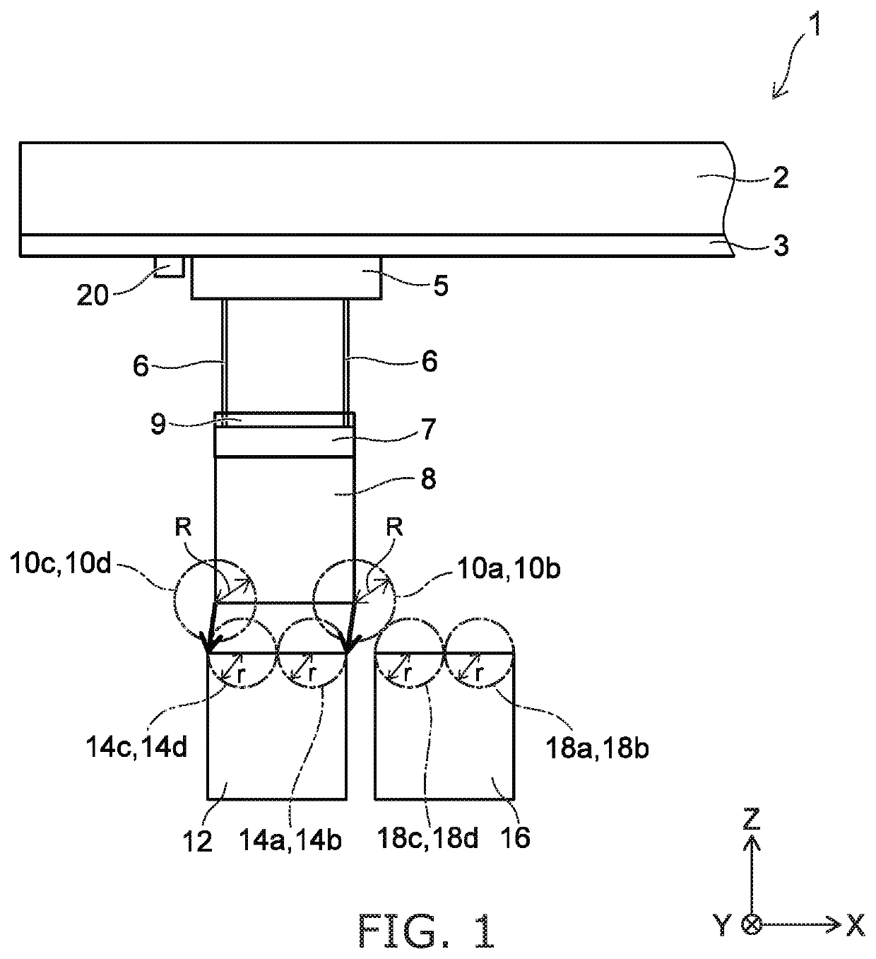
[0022]FIG. 1 is a schematic view illustrating a container crane.
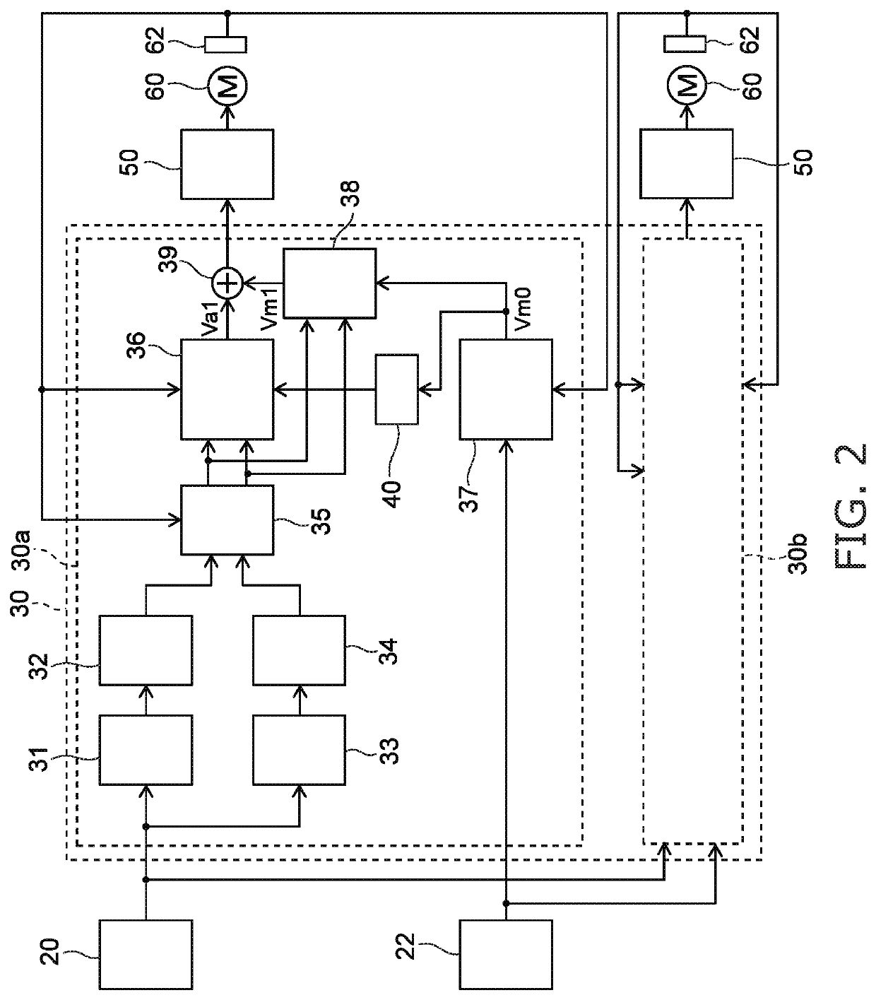
[0023]FIG. 2 is a block diagram illustrating an alignment apparatus of a position of the container according to the embodiment.
[0024]As shown in FIG. 1, a container crane 1 includes a trolley 5 moving transversely along a girder 3 provided on a lower side of a boom 2. The trolley 5 suspends a spreader 7 via a rope 6 and a head block 9. A container 8 is suspended via the spreader 7.
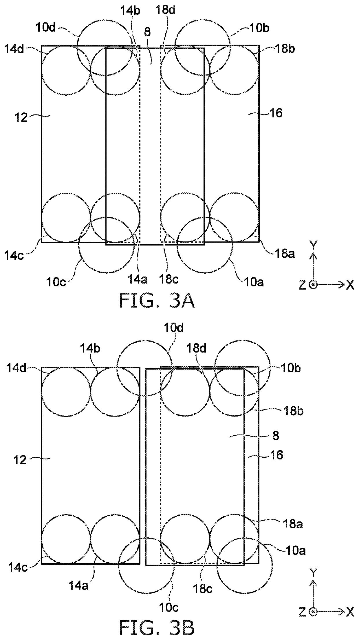
[0025]In the following description, a direction in which the trolley 5 moves transversely is taken as an X-axis direction. The trolley 5 is supported on the ground (plane surface) by a support of the container crane 1 not shown. The support of the container crane 1 can travel on a rail provided along a Y-axis direction orthogonal to the X-axis. It is assumed that the container crane 1 is placed on the plane surface including the X-axis and the Y-axis and the container 8 is suspended along a Z-axis direction orthogonal to the X-axis and the Y-a...
second embodiment
[0081]FIG. 5 is a block diagram illustrating an alignment apparatus according to the embodiment.
[0082]In the case of the embodiment, when the self-container 8 too approaches the container 12 at the target position in the alignment in the Z-axis direction, the alignment apparatus acts so as to keep away the self-container 8 from the target position. Thereby, the alignment apparatus can prevent the self-container 8 from colliding to a side surface of the container 12 at the target position.
[0083]An alignment apparatus 130 of the embodiment includes a control circuit 130b of the Z-axis direction. The control circuit 130b of the X-axis direction is the same as the case of the first embodiment.
[0084]The control circuit 130b includes the position measuring part 31 of the self-container, the calculator 32 for the automatic operation regions of the self-container, the position measuring part 33 measuring the automatic target position, the calculator 34 for the automatic operation regions of...
third embodiment
[0093]FIG. 7 is a block diagram illustrating an alignment apparatus of the embodiment.
[0094]FIG. 8 is a conceptual view for describing the action of the alignment apparatus of the embodiment.
[0095]In the case of the second embodiment, when the distance between the self-container 8 and the target position is close in the Z-axis direction, the speed reference signal is generated so as to keep away each other, and thereby the collision of the both side surfaces is prevented. In the alignment apparatus of the embodiment, the self-container 8 can be aligned to the target position smoothly by changing shapes of the automatic operation regions of the target position.
[0096]As shown in FIG. 7, an alignment apparatus 230 includes a control circuit 230b. The control circuit 230b acts for movement in the Z-axis direction. The control circuit 230b includes a calculator 234 in place of the calculator 34 for the automatic operation regions in the case of the second embodiment described above. The ...
PUM
 Abstract
Description
Claims
Application Information
 - R&D
- Intellectual Property
- Life Sciences
- Materials
- Tech Scout
- Unparalleled Data Quality
- Higher Quality Content
- 60% Fewer Hallucinations
Browse by: Latest US Patents, China's latest patents, Technical Efficacy Thesaurus, Application Domain, Technology Topic, Popular Technical Reports.
© 2025 PatSnap. All rights reserved.Legal|Privacy policy|Modern Slavery Act Transparency Statement|Sitemap|About US| Contact US: help@patsnap.com


