
Charge device and charging system

a charging device and charging system technology, applied in the direction of coupling device connection, process and machine control, instruments, etc., can solve the problems of autonomous mobile devices being unable to smoothly align with the charging device, or even being stuck, etc., to achieve smooth alignment, large rotational angle, and stable charging

Active Publication Date: 2021-08-05
PEGATRON
View PDF5 Cites 0 Cited by
  • Summary
  • Abstract
  • Description
  • Claims
  • Application Information

AI Technical Summary

Benefits of technology

The patent provides a charge device that can automatically align with an autonomous mobile device for charging. It includes a fixing base, a pivoting lever, and a charging arm that can rotate relative to the pivoting lever and the fixing base. This allows the charge device to have a larger rotational angle when the autonomous mobile device moves to it, ensuring smooth alignment and stable charging.

Problems solved by technology

However, when the autonomous mobile device is in the process of moving to the charge device, there may be an offset generated between the autonomous mobile device and the charge device, which often results in the autonomous mobile device being unable to smoothly align with the charge device, or even being stuck.

Method used


Image

  • Charge device and charging system
  • Charge device and charging system
  • Charge device and charging system

Examples


Embodiment Construction

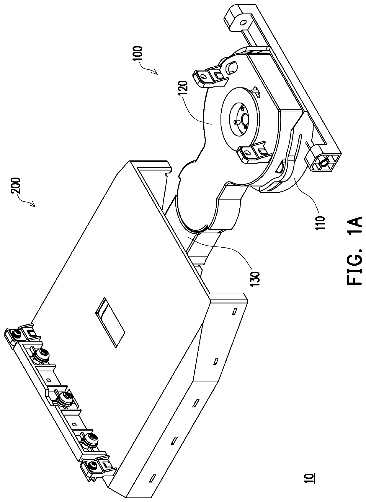
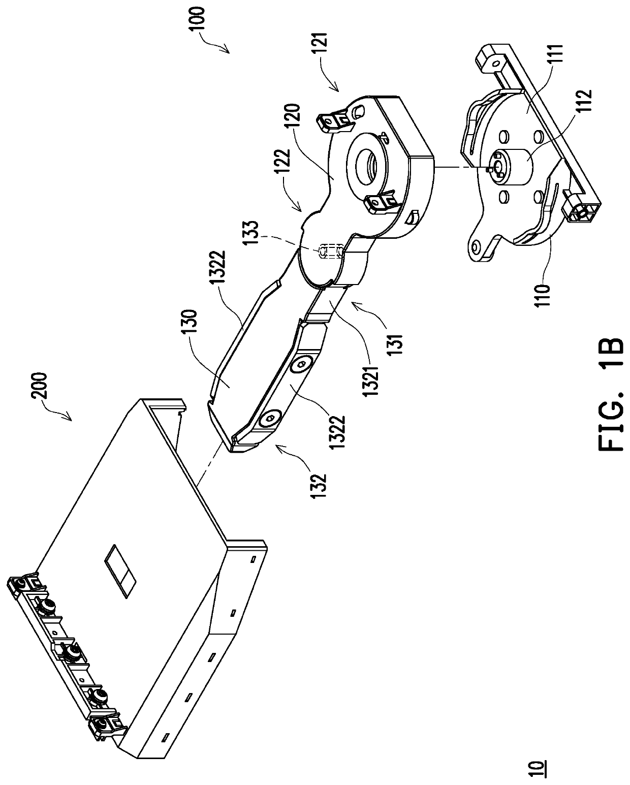
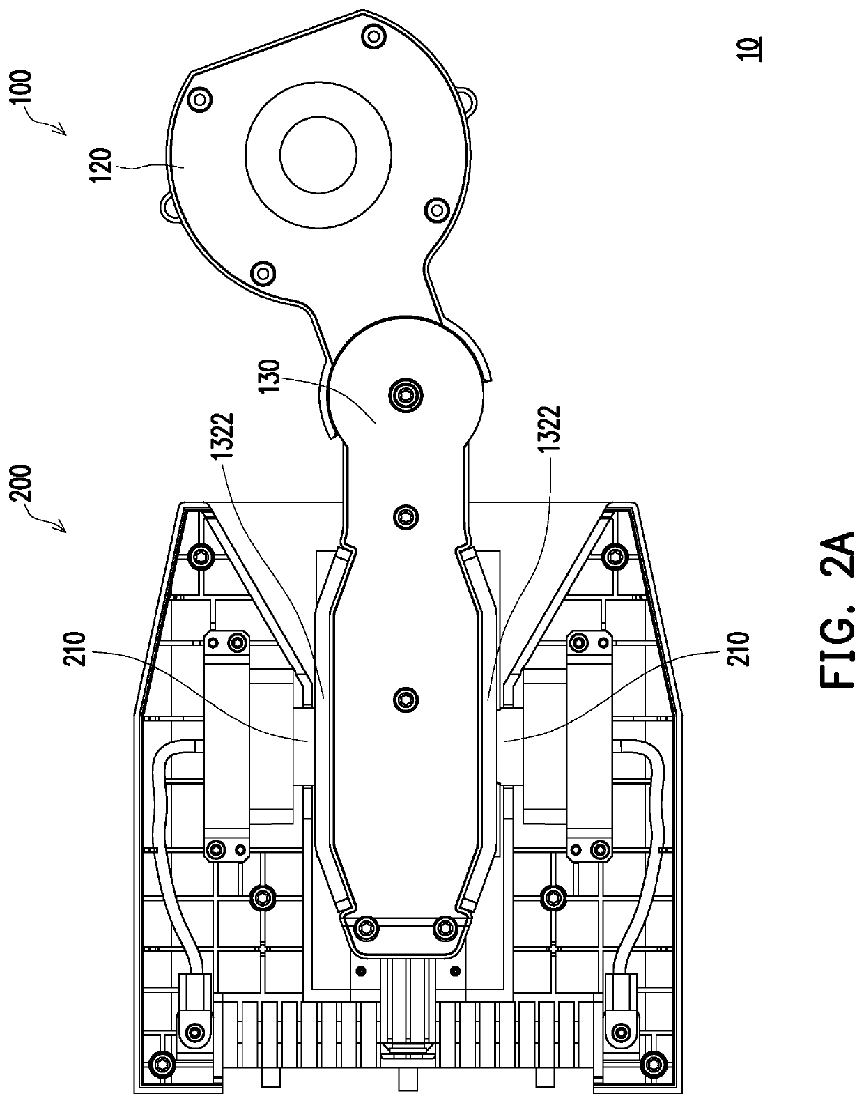
[0029]FIG. 1A is a three-dimensional schematic view of a charging system according to an embodiment of the disclosure. FIG. 1B is an exploded schematic view of the charging system in FIG. 1A. FIGS. 2A and 2B are bottom schematic views of the charging system in FIG. 1A in different states. It should be noted that a fixing base 110 is omitted in FIGS. 2A and 2B to show a pivoting lever 120 more clearly.

[0030]With reference to FIGS. 1A to 2B, a charging system 10 of the embodiment includes a charge device 100 and an autonomous mobile device 200. The charge device 100 is able to charge the autonomous mobile device 200. Here, the autonomous mobile device 200 is, for example, a high-current robot, but is not limited thereto. It should be noted that, in the embodiment, only a portion of a charging terminal of the autonomous mobile device 200 is illustrated, and the portion of the robot above the portion of the charging terminal is omitted to facilitate the description.

[0031]In the embodime...


PUM


Abstract

A charge device, including a fixing base, a charging arm pivoting lever, and a pivoting lever, is provided. The charging arm includes a first end portion and a second end portion. The pivoting lever includes a first portion and a second portion, and the first portion is pivotally connected to the fixing base. The pivoting lever is adapted to rotate relative to the fixing base, the second portion is pivotally connected to the first end portion, and the charging arm is adapted to rotate relative to the pivoting lever. A charging system is also provided.

Description

CROSS-REFERENCE TO RELATED APPLICATION[0001]This application claims the priority benefit of Taiwan application serial no. 109103423, filed on Feb. 4, 2020. The entirety of the above-mentioned patent application is hereby incorporated by reference herein and made a part of this specification.BACKGROUNDTechnical Field[0002]This disclosure relates to a charge device and a charging system, in particular to a charge device and a charging system related to an autonomous mobile device.Related Art[0003]In general, an autonomous mobile device is paired with a charge device for recharging. The charge device is usually set up at a location, and the autonomous mobile device is able to automatically move to the location to dock with the charge device for charging.[0004]However, when the autonomous mobile device is in the process of moving to the charge device, there may be an offset generated between the autonomous mobile device and the charge device, which often results in the autonomous mobile...

Claims


Application Information

Patent Timeline
Patent Type & Authority Applications(United States)
IPC IPC(8): B60L53/35H02J7/00G05D1/02G05D1/00
CPCB60L53/35G05D1/0088G05D1/0225H02J7/0042H01R13/6315H01R13/62933Y02T10/70Y02T10/7072Y02T90/12
Inventor CHUANG, HSIN-LINCHUANG, WEN-CHANG
Owner PEGATRON
Learn More