
Liquid crystal display

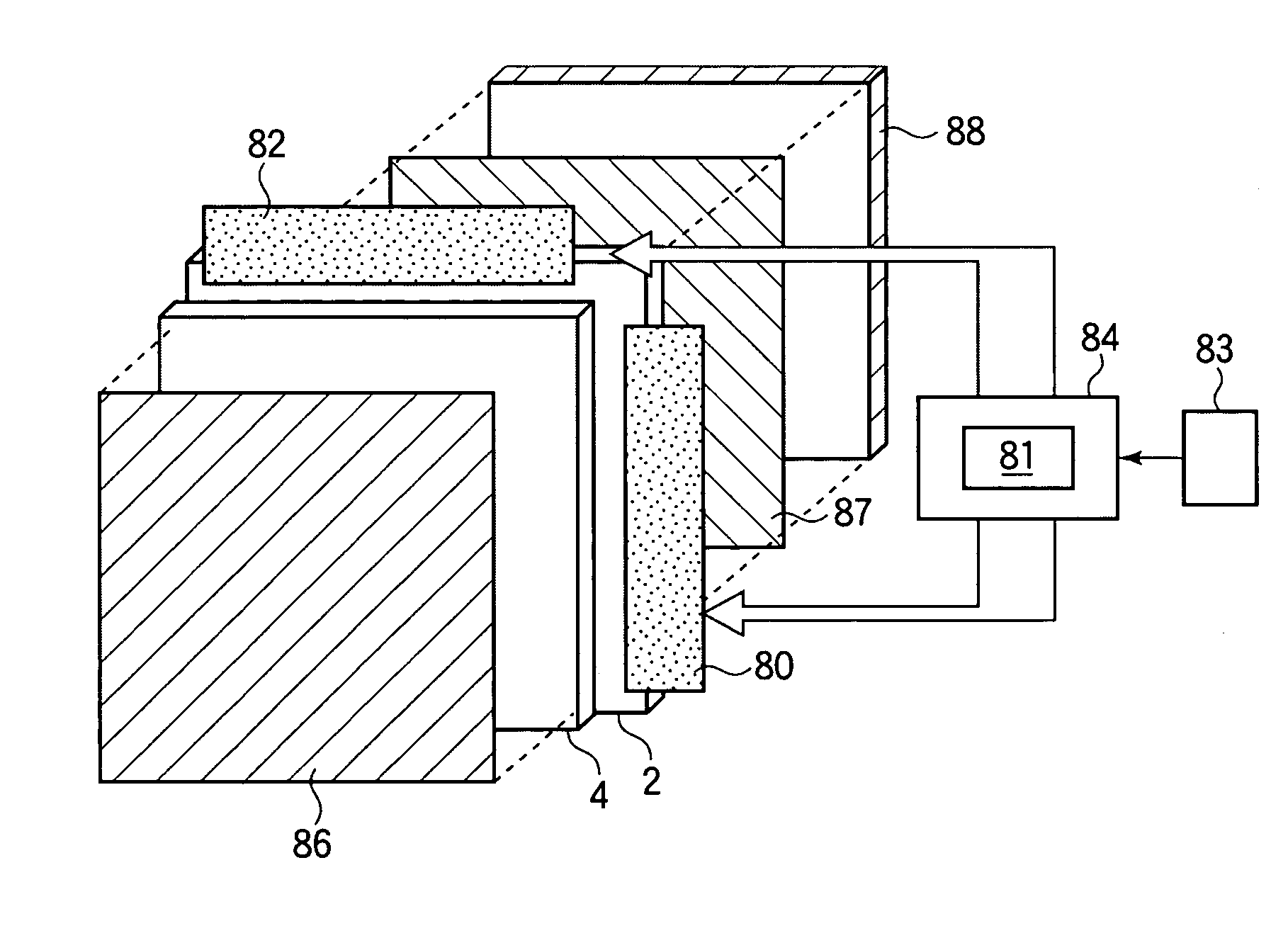
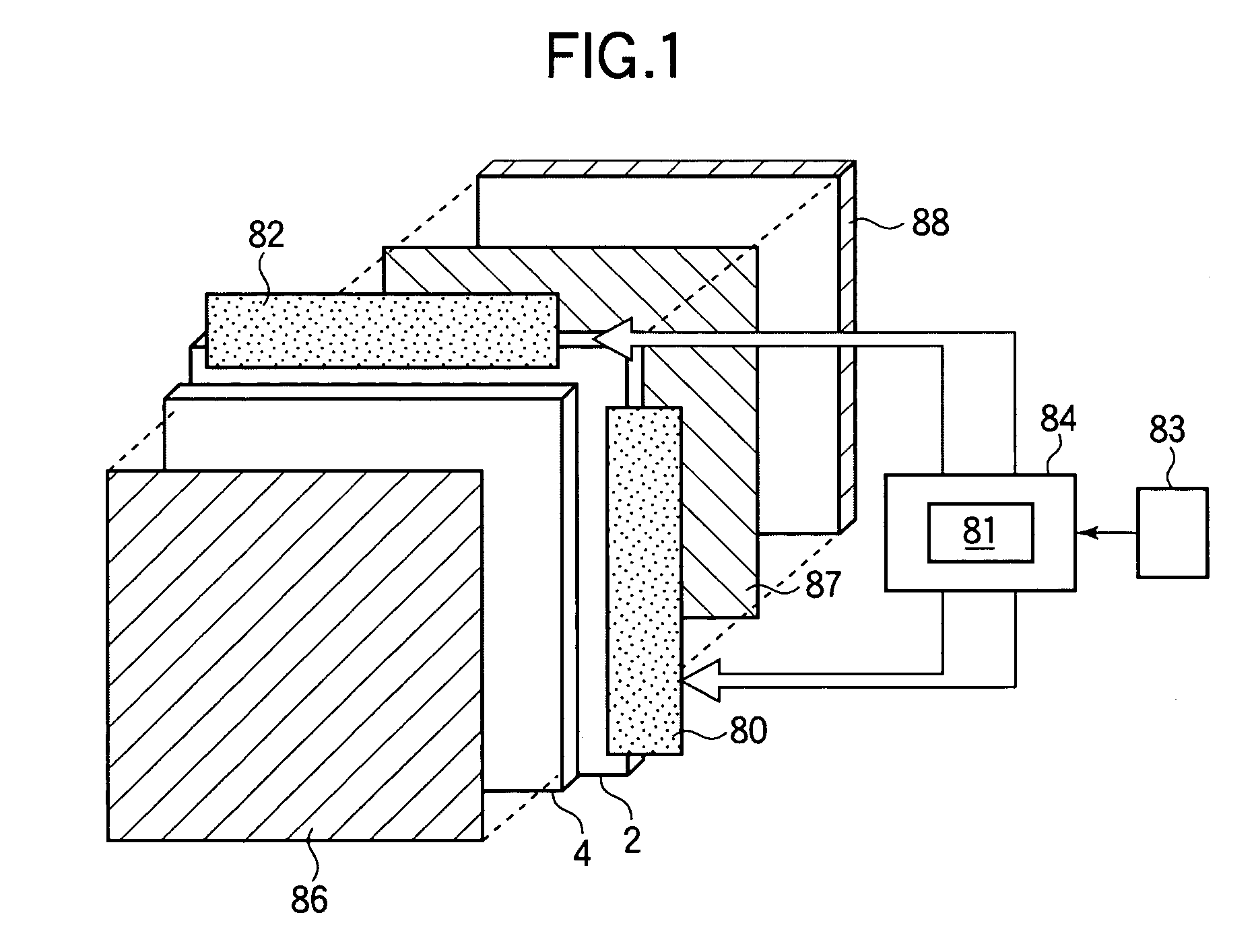
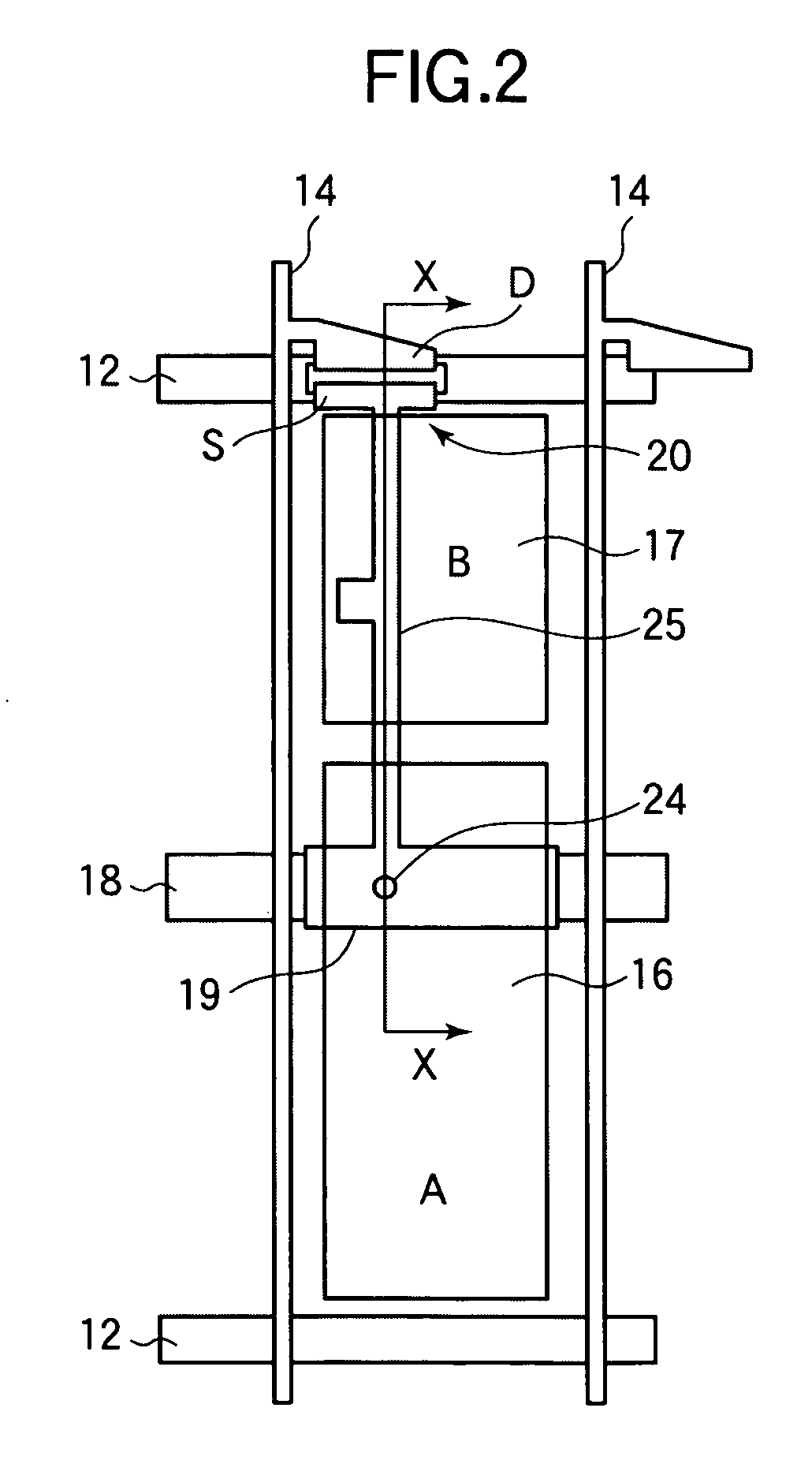
a liquid crystal display and display technology, applied in the field of liquid crystal display, can solve the problems of unsatisfactory viewing angle characteristics, and achieve the effect of wide viewing angle and high viewing angle characteristics

Inactive Publication Date: 2007-01-18
SHARP KK
View PDF14 Cites 23 Cited by
  • Summary
  • Abstract
  • Description
  • Claims
  • Application Information

AI Technical Summary

Benefits of technology

[0020] The invention makes it possible to provide a liquid crystal display having a wide viewing angle and high viewing angle characteristics.

Problems solved by technology

However, the liquid crystal display has a problem in that its viewing angle characteristics are not satisfactory because the display screen as a whole appears in a whitish color when it is viewed in a direction oblique to the same.

Method used


Image

  • Liquid crystal display
  • Liquid crystal display
  • Liquid crystal display

Examples


embodiment 1

[0086] In a liquid crystal of the present embodiment, the driving HT optimum conditions are used as the driving conditions of the driving HT method. FIG. 14 is a gradation conversion table showing high-luminance gradation values for obtaining high luminance in high-luminance frames and low-luminance gradation values for obtaining low luminance in low-luminance frames. The abscissa axis represents input gradations. The vertical axis on the left represents output gradations (converted gradations), and the vertical axis on the right represents luminance normalized with reference to the maximum luminance. The curve A connecting black rhombuses in the figure indicates low-luminance gradations, and the curve B connecting black squares indicates high-luminance gradation values. The curve C connecting crosses in the figure indicates normal luminance (predetermined luminance), and the curve D connecting circles in the figure indicates luminance after image processing according to the driving...

embodiment 2

[0102] A liquid crystal display of the present embodiment has a configuration similar to that of the liquid crystal display in Embodiment 1 except that the ratio A:B between the areas of a sub-pixel A and a sub-pixel B is 4:6.

[0103]FIG. 17 is a graph showing viewing angle characteristics of VA type liquid crystal displays. The abscissa axis represents gradations of image data to be displayed, and the ordinate axis represents γ-values. The curve connecting black rhombic symbols in the figure indicates characteristics of the liquid crystal display of the present embodiment obtained in a direction square to the same. The curve connecting black triangular symbols in the figure indicates characteristics of a liquid crystal display in a direction oblique to the same obtained by driving it using only the capacitive coupling HT method without using the driving HT method. The curve connecting black squares in the figure indicates characteristics of a VA type liquid crystal display according...


PUM


Abstract

The invention relates to a liquid crystal display used in a television receiver or a display section of an electronic apparatus and provides a liquid crystal display having a wide viewing angle and high viewing angle characteristics. The viewing angle characteristics of low gradations are improved by the capacitive coupling HT method. The viewing angle characteristics of high gradations above the intermediate gradation are improved by the driving HT method. A liquid crystal is driven using the capacitive coupling HT method and the driving HT method in combination to combine the effect of improvement of both methods, thereby improving the viewing angle characteristics of a liquid crystal display for a wide range from a low gradation to a high gradation.

Description

BACKGROUND OF THE INVENTION [0001] 1. Field of the Invention [0002] The present invention relates to a liquid crystal display used in a television receiver or a display section of an electronic apparatus. [0003] 2. Description of the Related Art [0004]FIGS. 22A and 22B show an example of a configuration of an MVA (Multi-domain Vertical Alignment) type liquid crystal display. FIG. 22A schematically shows a sectional structure of a liquid crystal display panel 101. FIG. 22B shows a structure of one pixel of the MVA type liquid crystal display panel 101 as viewed in a direction normal to the display screen. As shown in FIGS. 22A and 22B, the liquid crystal display panel 101 has a TFT substrate 102 on which thin film transistors (TFTs) 110 are formed and an opposite substrate 103 on which a common electrode and a color filter (CF) layer are formed. The substrates 102 and 103 are combined using a peripheral sealing material 105. A liquid crystal layer 104 is sealed between the substrates...

Claims


Application Information

Patent Timeline
Patent Type & Authority Applications(United States)
IPC IPC(8): G09G3/36
CPCG02F1/1362G02F2001/134345G02F2001/134354G09G2320/028G09G3/2074G09G3/3648G09G3/2025G02F1/134345G02F1/134354G02F1/133
Inventor KAMADA, TSUYOSHINAKANISHI, YOHEIUEDA, KAZUYAYOSHIDA, HIDEFUMITSUDA, HIDEAKI
Owner SHARP KK
Learn More