Liquid crystal lens using surface programming

a surface programming and liquid crystal technology, applied in optics, non-linear optics, instruments, etc., can solve the problems of non-reliable rubbing process, damage to the cell, non-uniformity and dust, etc., to improve the response of the lens to the control field, reduce aberration, and improve the effect of the control field respons

Inactive Publication Date: 2011-05-26
POINT FINANCIAL
View PDF20 Cites 11 Cited by
  • Summary
  • Abstract
  • Description
  • Claims
  • Application Information

AI Technical Summary

Benefits of technology

[0012]In the case of a planar alignment layer, the present invention can provide a fixed or non-tunable flat liquid crystal lens (or beam deviating device) by using suitable alignment layers to create in the ground state of the liquid crystal lens (or beam steering device) with the appropriate spatial distribution of index of refraction.
[0013]In some embodiments, the alignment layer is programmed such that the resulting effect on the liquid crystal is to place the liquid crystal at an orientation with respect to the control field that in the ground state (or otherwise at low control voltages close to the ground state) is in a linear range of change of index of refraction as a function of control voltage. Tunable liquid crystal lenses can have a portion of their range contain optical aberrations due to the relationship between orientation of the liquid crystal molecules and the control field, particularly at low angles close to the alignment layer. By programming larger pre-tilts than conventionally possible, a portion of the dynamic optical power range of a tunable liquid crystal lens may be lost, however, the improved response of the lens to the control field can greatly reduce aberrations at a lower range of control field tuning.
[0014]In all configurations of the present invention, it is possible to arrange liquid crystal layers in orthogonal directions to act on both polarizations of light, as well as to arrange layers having their directors in opposed direction to reduce an angular dependence associated with the liquid crystal lens (or beam steering) system.

Problems solved by technology

As it can be easily imagined, the rubbing process is not reliable and may damage the cell and create non uniformities and dust.
However those techniques must be approved yet for large scale, cost effective and reliable manufacturing processes.
However, the material system and the programming method used there did not allow the creation of “programmed surfaces” but let the created polymer network to “float” in the volume of the cell, FIG. 2 (Prior art).
This reduces the stability of the structures obtained and also creates volume aggregation of polymer and light scattering on director (average orientation of long molecular axes) orientation defects formed around those aggregations [V. V. Presnyakov; T. V. Galstian, Light Polarizer Based on Anisotropic Nematic Gel with Electrically Controlled Anisotropy of Scattering, Molecular Crystals and Liquid Crystals, Volume 413, Issue 1, 2004, pages 545-551].

Method used


Image

  • Liquid crystal lens using surface programming
  • Liquid crystal lens using surface programming
  • Liquid crystal lens using surface programming

Examples


Embodiment Construction

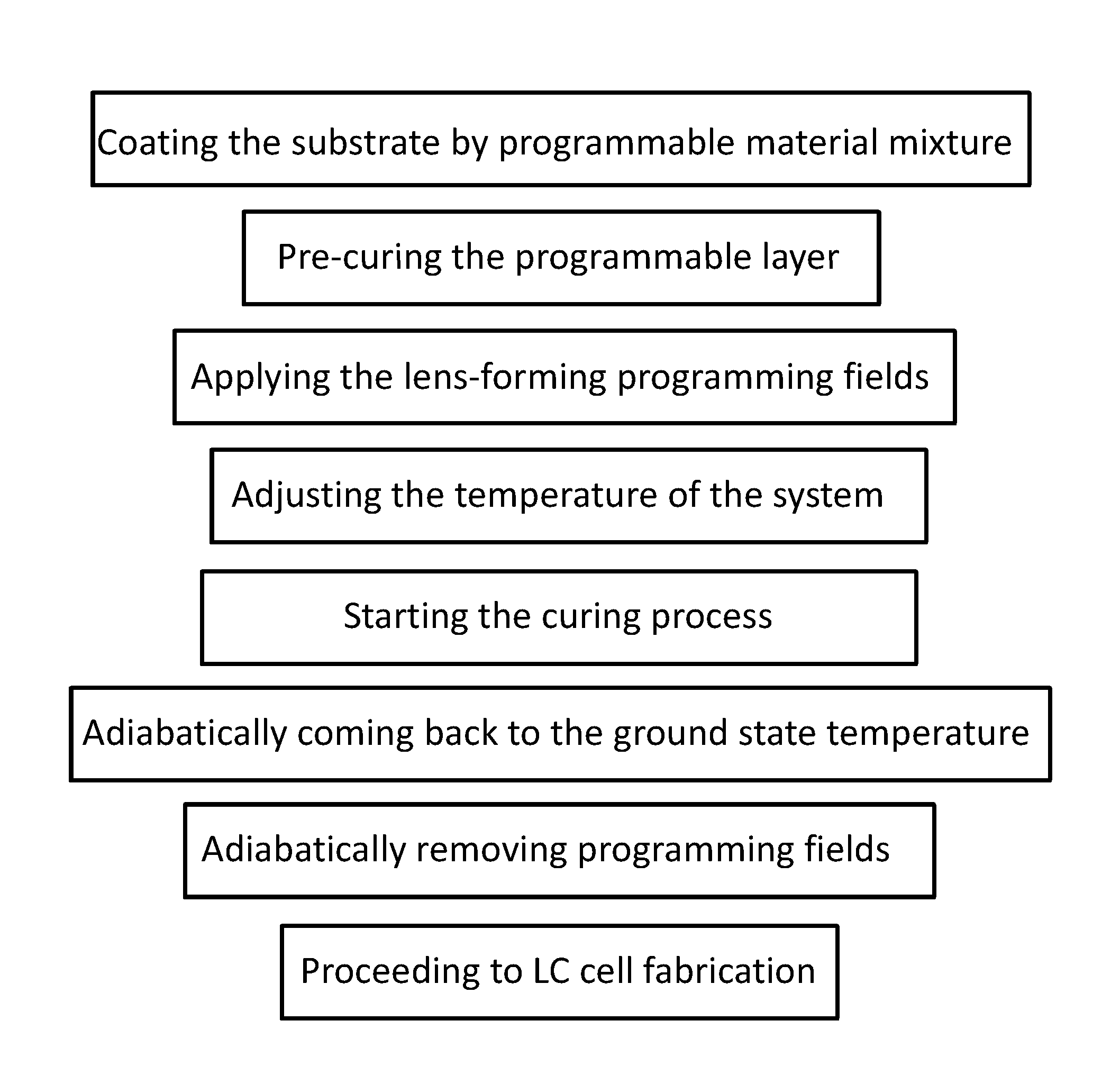
[0033]FIG. 3A schematically demonstrates the key principle of fabrication of an oriented LC cell (10) filled with surface polymer stabilized (optionally inter diffused) liquid crystal (11a). As shown in FIG. 3B, such a device has after its programming a programmed LC orientation in the ground state, namely without the typical electric field excitation. For simplicity of illustration, this orientation is shown as being of a spatially uniform direction, however, to form a lens, beam steering device or other imaging system optics, it will be appreciated that it is of a predetermined spatial profile.

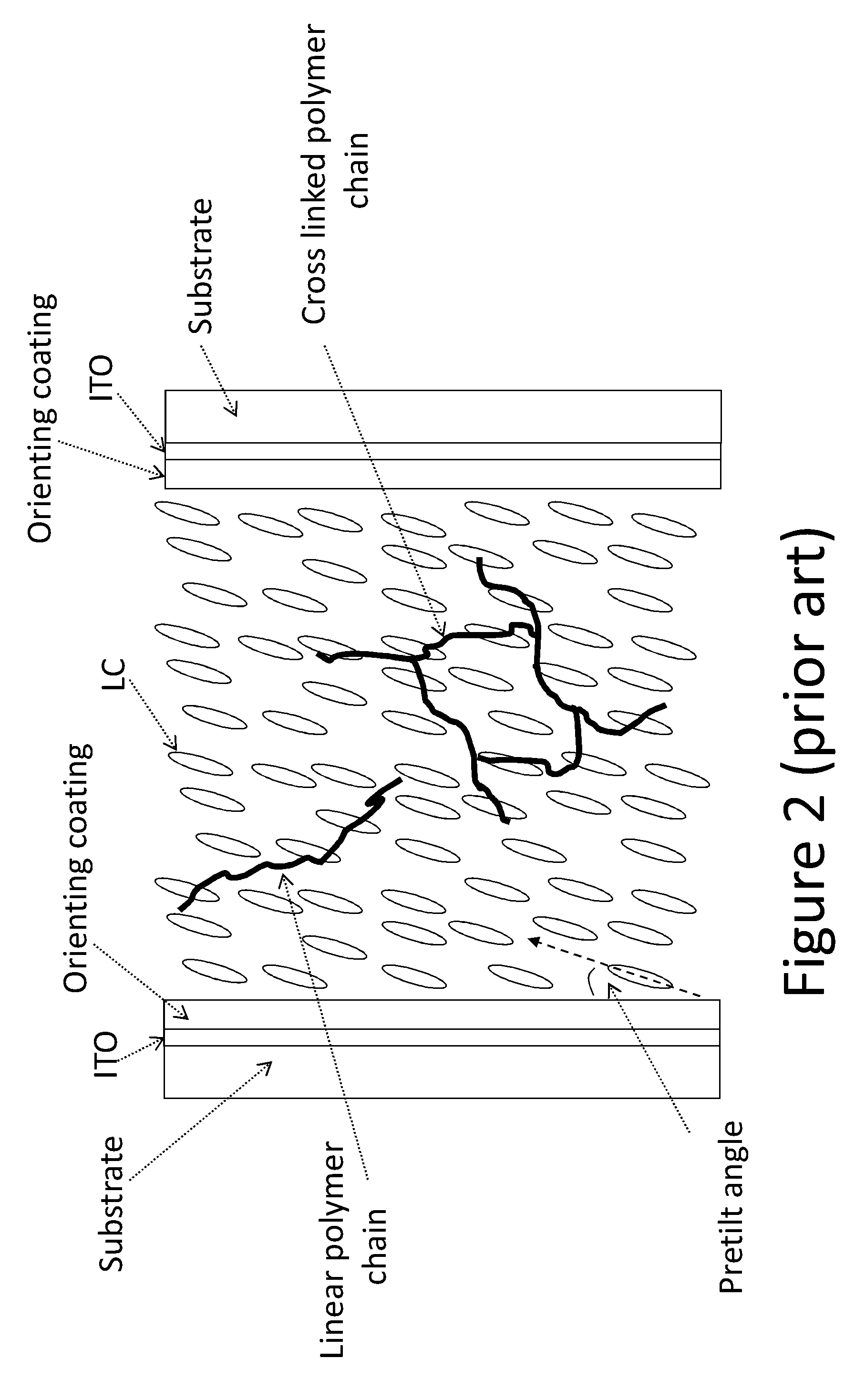
[0034]The surface “programmable” layer (16) is preferably chosen out of materials which have good orientational correlation (before and after the polymerization) with LC molecules. Examples of such materials can be different types of poyimides as used for rubbed alignment layers, reactive mesogenes (11b), etc.

[0035]The cell (10) shown here has no built-in electrodes to enable the use of vari...


PUM

PropertyMeasurementUnit
electricaaaaaaaaaa
magneticaaaaaaaaaa
optical propertiesaaaaaaaaaa

Abstract

A liquid crystal lens or beam steering device is made by programming alignment surfaces of the LC cell walls using a programming field to align the alignment surface molecules before fixing them. By setting the desired pre-tilt, the lens can operate in the absence of the control field, and power consumption by the control field can be reduced.

Description

TECHNICAL FIELD[0001]The present invention relates to liquid crystal (LC) lenses or beam steering devices and related manufacturing methods.BACKGROUND OF THE INVENTION[0002]LC lenses and beam steering devices are based on the alignment of LC molecules on substrates that are sandwiched together to form the LC cell. The interaction of LC with the surface of the substrate is of paramount importance for several reasons. Among the most important ones are A—the necessity to have a returning force (to enable the “free” relaxation) and B—to provide a pre-tilt angle to trigger a predictable reorientation direction.[0003]The traditional way of achieving the desired alignment of LC molecules was (and still is) the mechanical rubbing of the surface of the substrate [T. Ito and K. Nakanishi. Regularity and narrowness of the intervals of the microgrooves on the rubbed polymer surfaces for LC alignment. In SID International Symposium Digest of Technical Papers, Vol XXIII, pages 393-396, Boston, Ma...

Claims


Application Information

Patent Timeline
Patent Type & Authority Applications(United States)
IPC IPC(8): G02F1/1337
CPCG02F1/133711G02F1/133788G02F2001/133726G02F2203/24G02F2001/291G02F2001/294G02F2001/133765G02F1/133726G02F1/133765G02F1/291G02F1/294
Inventor GALSTIAN, TIGRAN
Owner POINT FINANCIAL
Why Eureka
Try Eureka