
Dual loop multi-frequency antenna

A multi-frequency antenna and loop antenna technology, applied in antennas, antenna arrays, circuits, etc., can solve the problems of high frequency bandwidth not meeting requirements, difficulties, difficulties in production, etc., achieve significant frequency reduction effect, reduce production difficulty and cost, The effect of increasing the bandwidth

Active Publication Date: 2008-01-16
昆山展腾电子科技有限公司
View PDF1 Cites 51 Cited by
  • Summary
  • Abstract
  • Description
  • Claims
  • Application Information

AI Technical Summary

Problems solved by technology

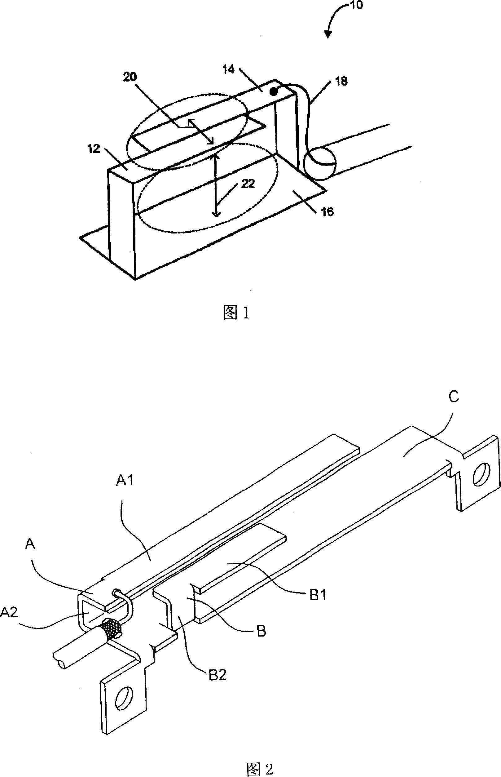
[0008] Although the above-mentioned antenna can form a multi-frequency operation, it has the following disadvantages: the distance between the first connecting part A2 and the second connecting part B2 is too close, so the bandwidth at high frequencies does not meet the requirements; The distance between the connecting portion A2 and the second connecting portion B2 is too short, and the first conductive sheet A1 and the second conductive sheet B1 extend in the same direction from the first connecting portion A2 and the second connecting portion B2 respectively, so the first The bending of the radiation part A and the second radiation part B will cause difficulties in manufacturing, and it will also be more difficult when the feeder is welded to the first conductive sheet

Method used


Image

  • Dual loop multi-frequency antenna
  • Dual loop multi-frequency antenna
  • Dual loop multi-frequency antenna

Examples


no. 1 example

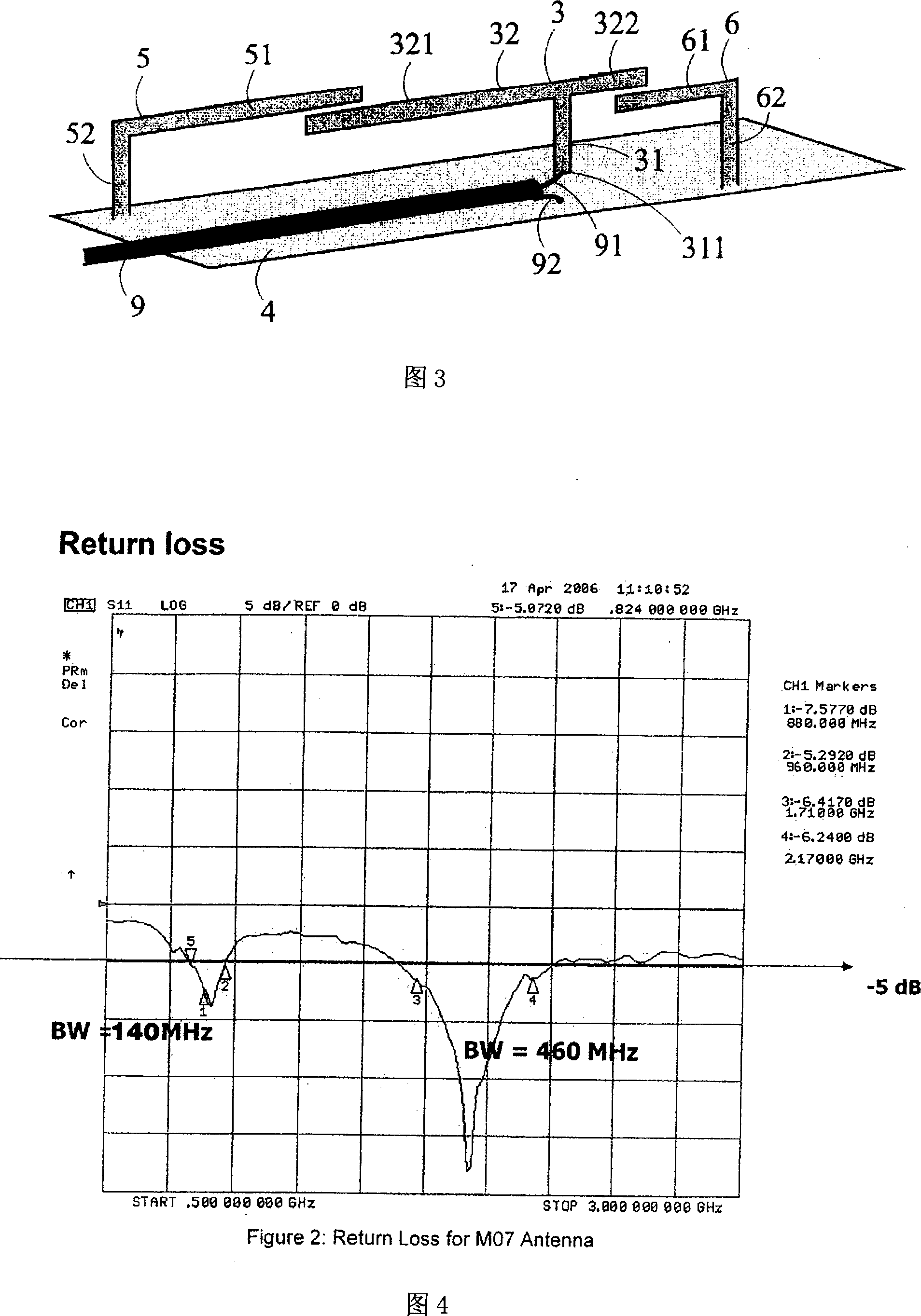
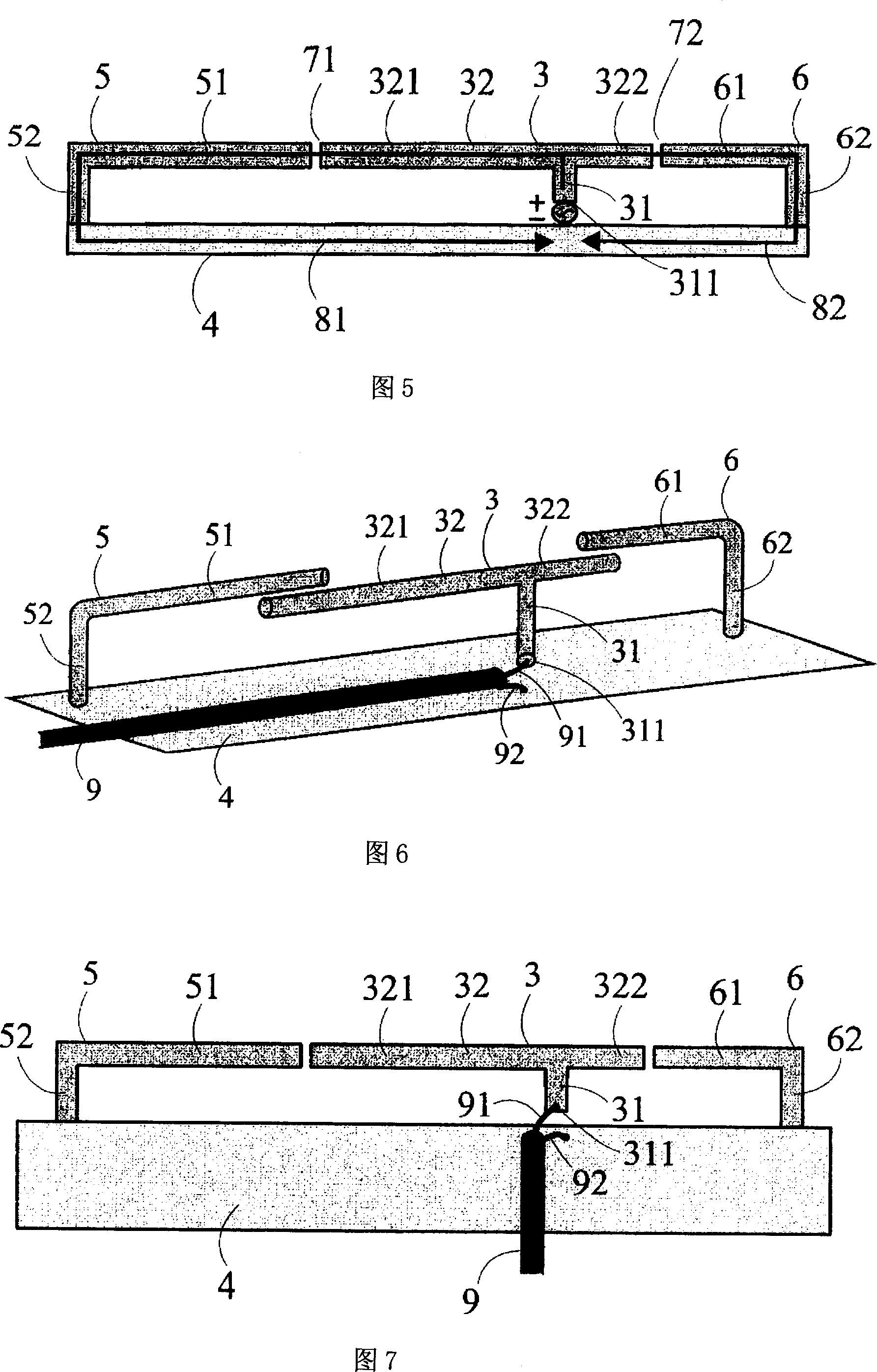
[0025] Please refer to Fig. 3, Fig. 3 is the first embodiment of the present invention, and this multi-frequency antenna is made up of a first conductor arm 5, a second conductor arm 6, a T-shaped metal radiator 3, two L-shaped metal radiators, It consists of a grounded metal surface 4 and a feed-in line 9, wherein the T-shaped metal radiator 3 is suspended in this embodiment, that is, it is not in contact with the grounded metal surface 4, but the T-shaped metal radiator 3 The bottom end 311 of the straight side 31 of the straight side 31 is connected with the signal positive end 91 of the feed-in line 9, so as to transmit the electric signal to the T-shaped metal radiator 3, while the signal negative end 92 of the feed-in line 9 is connected with the ground metal surface 4 Electrical connections.

[0026] The first conductor arm 5 and the second conductor arm 6 of the two L-shaped metal radiators are set up opposite to each other, and their long sides 51, 61 are directed to ...


PUM


Abstract

The invention relates to a double-loop multi-frequency antenna, with a T-shaped metal radiator provided with long sides at different lengths acting as a main body and two L-shaped metal radiators connected with the ground cooperated to form two loop antennas, which can respectively generate high-frequency and low-frequency operation modes. The invention utilizes a bidirectional structure to allow multi-frequency antenna to have enough frequency width at high frequency, and at the same time, to meet the usage demands at low frequency, so as to meet the system requirements of the frequency bands of DCS / PCS / UMTS high frequency and AMPS / GSM low frequency.

Description

technical field [0001] The present invention is a dual-loop multi-frequency antenna, especially a T-shaped metal radiator with unequal lengths as the main body, and two L-shaped metal radiators grounded to form two loop antennas. multi-frequency antenna. technical background [0002] In the wireless communication industry, personal mobile communication has already demonstrated its huge potential and business opportunities. During its evolution, many systems have been developed. The technologies and channels they use are different, and they are also in different regions and markets. However, this phenomenon also causes confusion and inconvenience to system suppliers and consumers. One of the most important points is that different systems use different frequencies, such as GSM900, DCS1800 and PCS1900. [0003] In order to make users more convenient, the industry has invested a lot of manpower to develop multi-band mobile phones. However, the first difficulty to be overcome i...

Claims


Application Information

Patent Timeline
Patent Type & Authority Applications(China)
IPC IPC(8): H01Q1/38H01Q5/00H01Q13/00H01Q21/00
Inventor 钟明勳邱宗文萧富仁林育庆蓝纯青
Owner 昆山展腾电子科技有限公司
Learn More