Aging power supply device with parallel input and series output

A series output and power supply device technology, applied in the direction of output power conversion device, AC power input conversion to DC power output, DC power input conversion to DC power output, etc. Problems such as voltage, energy waste, and large current

Active Publication Date: 2019-12-27
CENT SOUTH UNIV
View PDF10 Cites 8 Cited by
  • Summary
  • Abstract
  • Description
  • Claims
  • Application Information

AI Technical Summary

Problems solved by technology

[0005] (1) Use resistors or similar dummy loads to convert electrical energy into heat energy for consumption. Although this most primitive discharge method is simple and cheap, it causes a huge waste of energy. contrary to the theme of
At the same time, the heat dissipation of the resistance discharge device is difficult to deal with, the aging power consumption is large and the current is large, and the wire is empty and heats up seriously, which is easy to cause fire, electrical short circuit and other dangers
In addition, it is difficult to realize the continuous adjustment of the discharge current through resistance discharge.
[0006] (2) Adopt the constant voltage discharge method, use the common inverter on the market, and the discharge current is slightly smaller than the constant current value of the charger. Although this method can also feed back the energy of the charger to the grid, because it is a constant voltage method, it is very difficult It is difficult to simulate that the charger is in the state of constant current charging but the output voltage is slightly lower than the nominal value for a long time

Method used


Image

  • Aging power supply device with parallel input and series output
  • Aging power supply device with parallel input and series output
  • Aging power supply device with parallel input and series output

Examples


Embodiment 1

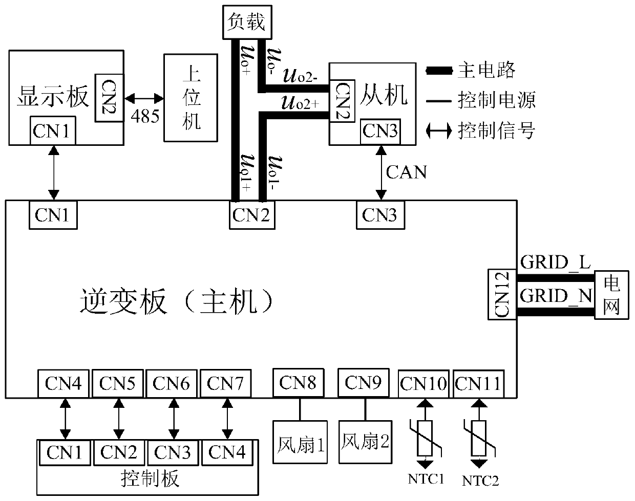
[0067] like figure 1 As shown, the control method of an aging power supply device disclosed in this embodiment is used to control an aging power supply device with parallel input and serial output, which consists of a master, a slave, a power supply module, a load device, a display board, a control Thermistor module composition.

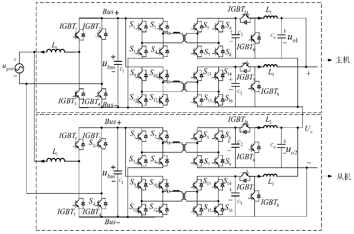
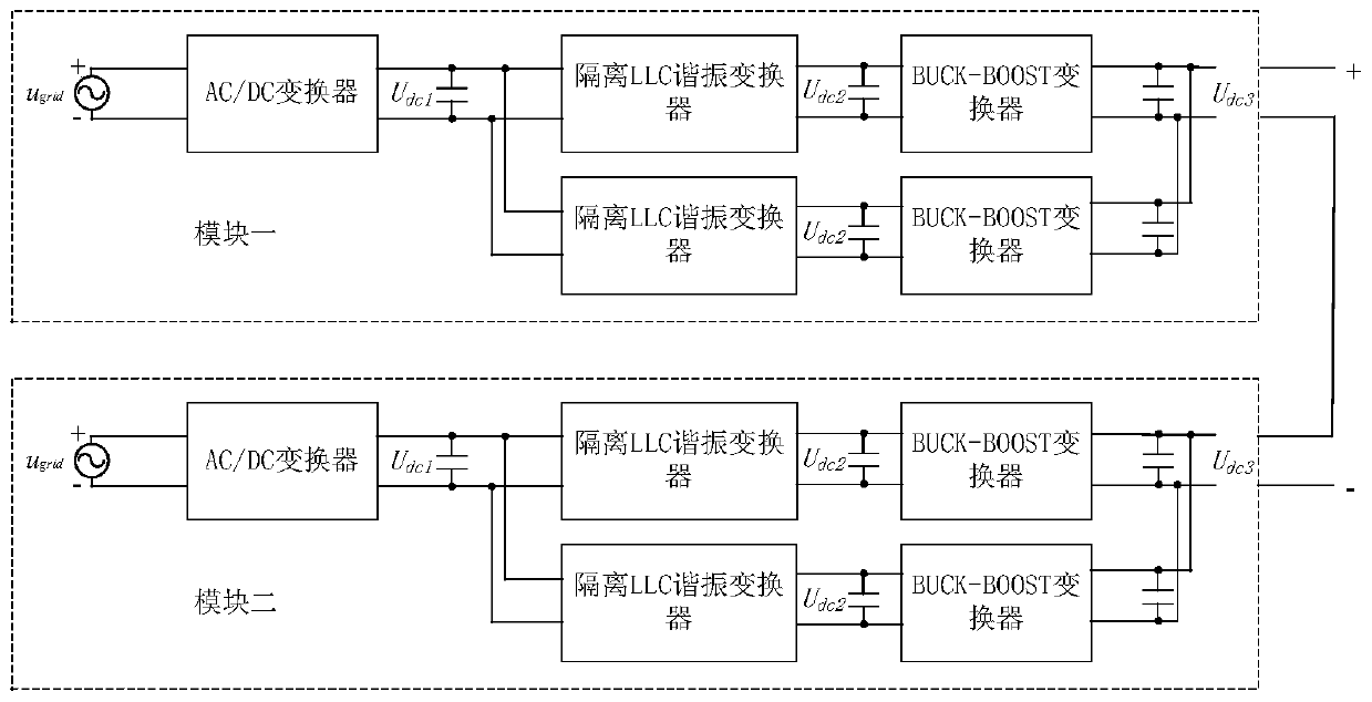
[0068] The internal topology of the host and the slave of the aging power supply device with parallel input and serial output is the same, the input terminals of the host and the slave are connected in parallel with the power grid of the power supply module, and the output terminal of the host is connected to the power grid of the power supply module through the output of the host After being connected in series with the output of the slave machine, it is connected with the load device, so as to realize the parallel connection of the input and the series connection of the output.

[0069] The host communicates with the slave through the CAN transmis...


PUM


Abstract

The invention discloses an aging power supply device with parallel input and series output and belongs to the field of power electronic system control. The device is mainly composed of a host, a slave, a power supply module, a load device, a display panel, a control panel, a first fan, a second fan, a first thermistor and a second thermistor module, wherein the host is connected with an input endof the slave in parallel, the host is then connected with a power grid of the power supply module, the output of the host and the output of the slave are connected in series and then connected with the load device, and the outputs are connected in series and then connected with the load device as an output end of the aging power supply device, and thereby input-parallel output-series is realized.The aging power supply device is advantaged in that internal topological structures of the host and the slave are the same, the internal topological structures of the host and the slave respectively comprise three control circuits including a single-phase AC / DC converter circuit, an isolation LLC resonant converter circuit and a bidirectional BUCK-BOOST converter circuit, energy can flow in two directions, a power grid is not polluted, loss is small, cost is low, and reliability and practicability are good.

Description

technical field [0001] The invention belongs to the field of power electronic system control, in particular to an aging power supply device. Background technique [0002] At present, the country is vigorously implementing energy conservation and emission reduction, promulgating national standards for electric vehicles, encouraging the development of electric vehicles, and green travel. 2015 is the beginning of the rapid development of electric vehicles, and there will be a large number of electric vehicles in the market. Very large, in order to meet the market demand, the electric vehicle charger and its energy-saving aging device are specially launched. [0003] On the one hand, it meets the needs of automobile manufacturers for the configuration of chargers, and on the other hand, it solves the aging problem of other charger manufacturers. Because the power of electric vehicle chargers is large, it consumes a lot of electric energy when it leaves the factory, and the elect...

Claims


Application Information

Patent Timeline
Patent Type & Authority Applications(China)
IPC IPC(8): H02M7/219H02M3/335H02M3/158H02J3/01
CPCH02J3/01H02M3/1582H02M3/1584H02M3/33576H02M7/219H02M1/0058H02M1/0083H02M3/1586Y02B70/10Y02E40/40
Inventor 但汉兵曾鹏胡子恒粟梅孙尧王辉刘永露熊文静徐菁涛
Owner CENT SOUTH UNIV
Why Eureka
Try Eureka