Multi-frequency multi-target selective wireless energy transmission method and system

A wireless energy transmission, multi-target technology, applied in the field of electromagnetic wave wireless energy transmission, can solve the problems of energy waste, low multi-target energy transmission efficiency, high energy transmission efficiency and so on.

Active Publication Date: 2020-03-13
UNIV OF ELECTRONICS SCI & TECH OF CHINA
View PDF7 Cites 4 Cited by
  • Summary
  • Abstract
  • Description
  • Claims
  • Application Information

AI Technical Summary

Problems solved by technology

An invention patent with the application patent number CN201810580731.6 discloses a method of frequency division multiple access to realize the selective energy transmission of multiple transmitting devices to multiple energy targets. This method uses different frequency signals to different The energy transmission of the powered target can realize the independent energy transmission of each target in the multi-target, so when the parallel energy transmission is performed on the selected multiple targets, almost no side lobes are generated, but each powered antenna can only receive Specified single frequency energy, the energy of other frequency points at the position of the powered antenna is greatly wasted, which reduces the efficiency of multi-target energy transmission
[0005] To sum up, the current multi-target selective wireless energy transmission method still has some inherent defects, and it is difficult to take into account the low side lobe and high energy transmission efficiency in the case of arbitrary multi-target selective energy transmission.

Method used


Image

  • Multi-frequency multi-target selective wireless energy transmission method and system
  • Multi-frequency multi-target selective wireless energy transmission method and system
  • Multi-frequency multi-target selective wireless energy transmission method and system

Examples


Embodiment Construction

[0056] The present invention will be further described below in conjunction with the accompanying drawings and embodiments.

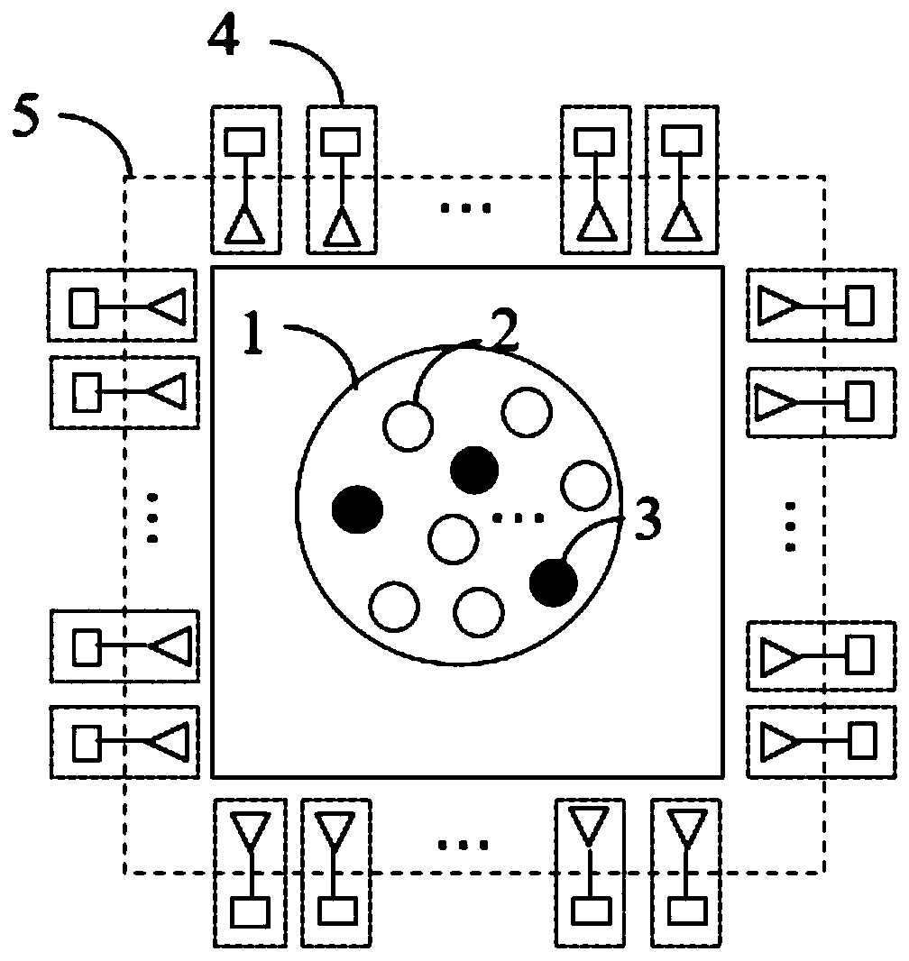
[0057] This embodiment provides a multi-frequency and multi-target selective energy transmission method and system. The structural diagram of the system is as follows figure 1 As shown, 1 represents the receiving device group ECG, 2 is the selected device not to be powered, 3 is the selected device to be powered, and 4 is the transmitting device TR 2 ~TR N , 5 is the transmitter group TRM.

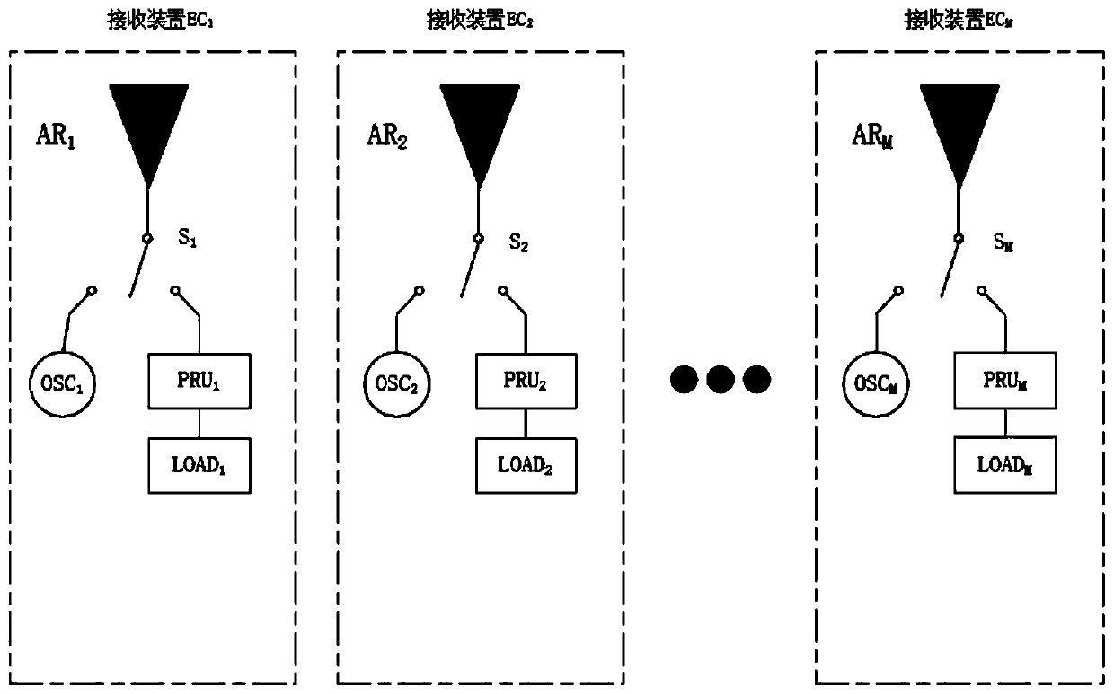
[0058] The structure of the receiving device group is as follows figure 2 shown, including: powered antenna AR 1 ~ AR M , used to transmit sinusoidal detection signal and receive energy transmission signal; signal source OSC 1 ~OSC M , used to generate the detection signal of the selected frequency; the load LOAD 1 ~LOAD M , is the equipment load that needs to be powered, driven by DC; the rectifier unit PRU 1 ~PRU M , used to place the receiving device E...


PUM


Abstract

The invention discloses a multi-frequency multi-target selective wireless energy transmission method and system, and belongs to the technical field of electromagnetic wave wireless energy transmission. The method comprises the following steps: constructing a receiving device group and a transmitting device group of the multi-frequency energy transmission system; discretizing an energy transmissionbandwidth range adopted by the system according to the measured maximum multipath time delay in the energy transmission environment, and extracting an energy transmission channel parameter of the energy transmission system at each frequency point; selecting an optimal energy transmission frequency point according to the extracted energy transmission channel parameters and a calculation formula; and determining an optimal feed-in signal corresponding to the selected frequency point by using an optimization algorithm to realize multi-target selective parallel energy transmission. According to the method, the problem that the energy transmission efficiency and the sidelobe value are difficult to consider in an existing multi-target selective energy transmission technical method is solved, and efficient and low-sidelobe multi-target selective parallel energy transmission is achieved.

Description

technical field [0001] The invention belongs to the technical field of electromagnetic wave wireless energy transmission, and in particular relates to a multi-frequency and multi-target selective energy transmission method and system. Background technique [0002] Wireless Power Transfer (WPT) is a research frontier in the current field of energy transmission, and it is also a research hotspot that has attracted much attention from the scientific and industrial circles in recent years. Compared with wired energy transmission, WPT can completely get rid of the shackles of power transmission cables, and can provide uninterrupted energy supply to electronic equipment anytime, anywhere, conveniently and flexibly around the clock. It is a revolutionary energy transmission technology that can be widely used In various fields of the national economy, its scientific research significance and application value are no less than today's wireless communication technology. [0003] At p...

Claims


Application Information

Patent Timeline
Patent Type & Authority Applications(China)
IPC IPC(8): H04W24/02H04B17/382H04B17/391
CPCH04W24/02H04B17/382H04B17/391
Inventor 钟成赵德双刘要红包金龙
Owner UNIV OF ELECTRONICS SCI & TECH OF CHINA
Why Eureka
Try Eureka