Bilateral thin-wall barrel port inward curling machine

A crimping machine and thin-walled technology, applied in the field of machinery and equipment, can solve the problems of low production efficiency, poor machining accuracy, and inability to mass-produce, and achieve the effects of reducing manpower usage, improving symmetry accuracy, and improving automation rate.

Inactive Publication Date: 2020-03-31
ZJMECH TECH
View PDF9 Cites 0 Cited by
  • Summary
  • Abstract
  • Description
  • Claims
  • Application Information

AI Technical Summary

Problems solved by technology

The production efficiency is low, mass production is impossible, and the processing accuracy is poor

Method used


Image

  • Bilateral thin-wall barrel port inward curling machine
  • Bilateral thin-wall barrel port inward curling machine

Examples


Embodiment 1

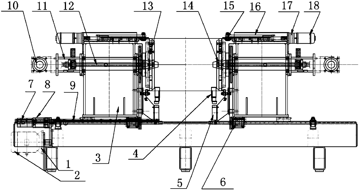
[0052] Such as figure 1 As shown, this application adopts a main body mechanism with relative movement of tooling boxes 3 on both sides of a reference working surface. The first motor 1 is installed on the left side of the application, and the first motor 1 is a servo motor; the first reducer 2 is installed On the right side of the first motor 1, the first reducer 2 is a planetary reducer; the hexagonal drive shaft is connected to the output hole of the first reducer 2 and runs through the bottom of the tooling box 3 on both sides, and the tooling box 3 on both sides Two sprockets 6 are arranged on the hexagonal transmission shaft at the bottom, and the sprocket 6 is fixedly connected with the bottom of the tooling box 3. The main movement of the workpiece forming is driven by the first motor 1 through the first reducer 2 to rotate the hexagonal transmission shaft. Each group of sprocket chain pairs of the workpiece boxes 3 on both sides transmits the torque to the workpiece p...

Embodiment 2

[0054] The displacement of the tooling box 3 on both sides of the application is realized by the linkage screw 9, the second motor 7 is installed above the first motor 1, and the model of the second motor 7 is ECMA-C20807RS; the second reducer 8 is installed on The right end of the second motor 7, the model of the second reducer 8 is PLF80-10; the left side of the linkage screw 9 is connected to the output hole of the second reducer 8 and runs through the bottom of the tooling box 3 on both sides, The linkage screw 9 is arranged on the front side of the hexagonal transmission shaft, and the two do not affect each other; the displacement of the tooling box 3 is driven by the second motor 7 through the second reducer 8 to rotate the linkage screw 9, and is installed on both sides of the linkage screw 9 The tooling box body 3 begins to move toward each other, and the sprocket wheel 6 fixedly installed on the bottom of the tooling box body 3 follows the tooling box body 3 displacem...

Embodiment 3

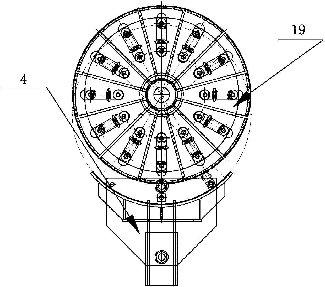
[0056] The core-pulling positioning mechanism 11 of the present application penetrates through the middle of the tooling box body 3, and the left and right core-pulling positioning mechanisms 11 are on the same axis. The core-pulling positioning mechanism 11 includes: a core-pulling cylinder 10 , a core-pulling rod 12 , and a core-pulling tower head 14 . The core-pulling cylinder 10 is located at the tail end of the core-pulling positioning mechanism 11. The model of the core-pulling cylinder 10 is SC150X50. The front end of the core-pulling cylinder 10 is provided with a core-pulling rod 12, which is installed inside the tooling box 3 , The front end of the core-pulling rod 12 is provided with a core-pulling tower head 14, the core-pulling tower head is provided with 12 expansion flaps 19, and the outer ring of the core-pulling tower head is provided with a workpiece positioning account plate 13. The loading and unloading positioning of the workpiece generates relative motion...


PUM


Abstract

The invention provides a bilateral thin-wall barrel port inward curling machine. The bilateral thin-wall barrel port inward curling machine is characterized by comprising a first motor, a hexagonal transmission shaft, a chain wheel, a second motor, a linkage lead screw, tool equipment boxes, double-rod air cylinders, workpiece curling hook forming mechanisms, and core-pulling positioning mechanisms, wherein a first speed reducer is arranged at the right side of the first motor; the hexagonal transmission shaft penetrates into an output hole of the first speed reducer; the chain wheel is arranged on the hexagonal transmission shaft; a second speed reducer is arranged above the second motor; the linkage lead screw penetrates into an output hole of the second speed reducer; the tool equipmentboxes are respectively arranged at the left side and right side of the linkage lead screw; the double-rod air cylinders are arranged at the lower sides of workpiece positioning expansion discs; the workpiece curling hook forming mechanisms are arranged at the upper sides of the tool equipment boxes; and the core-pulling positioning mechanisms are inserted in the middle parts of the tool equipmentboxes. The bilateral thin-wall barrel port inward curling machine is convenient for supporting the production of an automatic assembly line and increasing the automation rate, reduces the use of manpower, and effectively improves the production efficiency and processing accuracy.

Description

technical field [0001] The present application relates to the field of mechanical equipment, in particular to a double-sided thin-wall barrel port inward crimping machine. Background technique [0002] There are many types of similar machines at home and abroad, which are mainly used for the inward curling of the outer tank port of the water heater. Generally, the barrel of the workpiece is placed vertically on the working plane of the machine, and a single fixture is used. The two sides of the workpiece need to be clamped twice. forming. Production efficiency is low, mass production is impossible, and processing accuracy is poor. Water heater products are for civil use, and the production batch is generally large. This process needs to be equipped with a large number of similar machines to meet the requirements of the production batch. Contents of the invention [0003] (1) Technical problems to be solved [0004] In view of the above technical problems, the present ap...

Claims


Application Information

Patent Timeline
Patent Type & Authority Applications(China)
IPC IPC(8): B21D19/10B21D43/00B21D51/18
CPCB21D19/10B21D43/003B21D51/18
Inventor 宋敬儒马林林
Owner ZJMECH TECH
Why Eureka
Try Eureka