Porous flow-limiting noise-reducing orifice plate and flow-limiting noise reducer formed by same

A technology of restricting orifices and noise-reducing holes, applied in the direction of pipes/pipe joints/fittings, mechanical equipment, pipe components, etc. The effect of better current limiting and noise reduction, sufficient fluid development, and reduced extreme value difference

Active Publication Date: 2020-04-17
SICHUAN UNIV
View PDF18 Cites 2 Cited by
  • Summary
  • Abstract
  • Description
  • Claims
  • Application Information

AI Technical Summary

Problems solved by technology

For the conventional multi-hole flow-limiting orifice, on the one hand, after the fluid flows through the multi-hole flow-limiting orifice, the flow rate changes abruptly, first increases suddenly and then decreases rapidly to a stable value. The relationship between the static pressure energy and the kinetic energy described in the equation shows that the static pressure energy at the center of the orifice plate behind the plate is the smallest, so that the flow stream converges to the center of the orifice plate as a whole, resulting in the uneven velocity distribution behind the plate; on the other hand, due to the There is a large number of vortices in the recirculation zone in the gap, resulting in a large pressure loss
Large changes in pressure and velocity, uneven distribution and the existence of a large number of vortices make the overall flow stability of the medium behind the plate poor
[0004] In addition, the conventional multi-hole flow-restricting orifice also has the defect of high decibel noise behind the

Method used


Image

  • Porous flow-limiting noise-reducing orifice plate and flow-limiting noise reducer formed by same
  • Porous flow-limiting noise-reducing orifice plate and flow-limiting noise reducer formed by same
  • Porous flow-limiting noise-reducing orifice plate and flow-limiting noise reducer formed by same

Examples


Embodiment 1

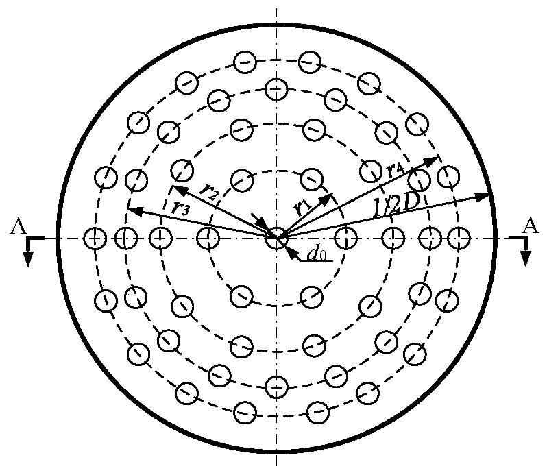
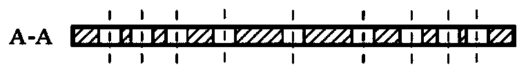
[0045] The porous current-limiting and noise-reducing orifice plate disclosed in this embodiment has a structure such as Figure 3A , the installation method is as follows Figure 9 shown. The porous current-limiting and noise-reducing orifice of this embodiment has a diameter of 203mm, a thickness of 12mm, a radius of 16mm, and a number of 25. The number of flow-limiting holes from the center of the orifice to the edge The order is: 1, 6, 8, 10, and the radius difference of the adjacent concentric circles where the flow limiting hole is located is: 34mm, 26mm, 18mm. The fluid medium used in the porous flow-limiting and noise-reducing orifice of this embodiment is water vapor with an inlet pressure of 1.56 MPa and a mass flow rate of 0.85 kg / s. The porous current-limiting and noise-reducing orifice plate is directly welded into the pipeline to achieve the effect of current-limiting and noise-reducing.

[0046] Comparative example is Figure 4A Compared with the multi-hole ...

Embodiment 2

[0048] The current limiting noise reducer disclosed in this embodiment has a structure such as Figure 10 As shown, its composition includes four porous current-limiting and noise-reducing orifice plates, two different-diameter pipes, a straight pipe section, and two flanges; the orifice plates at all levels adopt the concentric circle radius difference of the present invention in an arithmetic sequence arrangement , The interstage orifice plate is welded to the pipeline, and the two ends are connected to the inlet and outlet pipelines with flanges, forming a four-stage porous current limiting and noise reducer as a whole.


PUM

PropertyMeasurementUnit
Diameteraaaaaaaaaa

Abstract

The invention provides a porous flow-limiting noise-reducing orifice plate and a flow-limiting noise reducer formed by the same. According to the porous flow-limiting noise-reducing orifice plate, a flow-limiting orifice is arranged in the center of the orifice plate, other flow-limiting orifices are arranged in a group of concentric circles in an annular mode, the number of the flow-limiting orifices positioned on concentric circles with different radii gradually increases from inside to outside, the center distances of adjacent flow-limiting orifices positioned on the same concentric circlecircumference are the same, and the radius difference of adjacent concentric circles is arranged in an equal difference series from the center to the edge of the orifice plate. The flow-limiting noisereducer is composed of a pipe section and at least one porous flow-limiting noise-reducing orifice plate arranged in the pipe section, and connecting flanges are arranged at two ends of the pipe section. Compared with a conventional porous flow-limiting noise-reducing orifice plate, the noise-reducing capacity is improved, and the pressure loss is obviously reduced.

Description

technical field [0001] The present invention relates to the technical field of reducing pipeline medium pressure and noise, in particular to flow-limiting orifice technology, in particular to a multi-hole flow-limiting and noise-reducing orifice that needs to simultaneously reduce pressure and noise in large-pressure-drop pipelines and its Constituted current limiting noise reducer. Background technique [0002] The fluid flows through the porous orifice plate with a suddenly reduced cross-section in the pipeline, and the fluid is partially blocked, which will cause the pressure of the fluid behind the plate to decrease and the flow rate to increase. There is a certain pressure difference between the front and back of the orifice plate. For a certain aperture, the flow rate through the orifice plate increases with the increase of the pressure difference between the front and back of the orifice plate. The flow velocity at the hole reaches the speed of sound. At this time, n...

Claims


Application Information

Patent Timeline
IPC IPC(8): F16L55/027F16L55/033
CPCF16L55/02718F16L55/033
Inventor 吉华李倩王天豪蒋森
Owner SICHUAN UNIV
Why Eureka
Try Eureka