Auxiliary device of number tube machine

An auxiliary device and number tube technology, which is applied in the field of number tube machines, can solve problems such as line tube damage, and achieve the effect of reducing friction and avoiding damage

CN111114147BActive Publication Date: 2020-12-01李钢
10 Cites 0 Cited by

Patent Information

Authority / Receiving Office
CN · China
Patent Type
Patents(China)
Current Assignee / Owner
Publication Date
2020-12-01

Smart Images

  • Figure 1
    Figure 1
  • Figure 2
    Figure 2
  • Figure 3
    Figure 3
Patent Text Reader

Abstract

The invention discloses an auxiliary device of a cable marker and relates to the field of cable markers. The auxiliary device of the cable marker comprises a bottom plate, the cable marker, moving blocks, driving parts, fixing plates, main shafts, wheel discs and first motors, wherein matching holes are formed in the positions, at one side of an inlet and one side of an outlet of the cable marker,of the bottom plate; the moving blocks are positioned in the matching holes, and the driving parts are in power connection with the moving blocks; the fixing plates are symmetrically arranged at theupper end faces of the moving blocks, and the upper end faces of the fixing plates are provided with shaft grooves; the wheel discs are detachably connected with the main shafts, the two ends of eachmain shaft are placed in the corresponding shaft grooves, and the wheel discs are used for winding a pipeline; and the first motors correspond to the moving blocks one by one, and the first motors arefixed on one of the fixing plates and used for driving the corresponding main shaft to rotate. When the cable marker starts to work, the driving parts enable a cable pipe to always coincide with thecentral axis where the inlet and the outlet of the cable marker are located, so that the included angle between the cable pipe and the central axis where the inlet and the outlet of the cable marker are located is eliminated, the friction force between the cable marker and the cable pipe is effectively reduced, and the cable pipe is prevented from being damaged due to the friction force.
Need to check novelty before this filing date? Find Prior Art

Description

technical field

[0001] The invention relates to the field of number tube machines, in particular to an auxiliary device for number tube machines. Background technique

[0002] Number tube machine, also known as line number printer, referred to as line number machine and number printing machine. It can print characters on PVC sleeves, heat shrinkable tubes, special self-adhesive labels, and marking tapes. It is generally used for electrical control, power distribution, and switchgear secondary line identification. Special equipment for wire identification, which can meet the needs of power plants, electrical equipment factories, substations, and wire identification in the power industry. At present, the computer line number printer (or electronic line number printer) is widely used, which belongs to the thermal transfer printer, and has its own keyboard, which is easy to operate and easy to use.

[0003] The applicant found that: since the wire tube is usually wound on the ...

Examples

Embodiment Construction

[0028] In order to make the object, technical solution and advantages of the present invention clearer, the present invention will be described in further detail below in conjunction with specific embodiments and with reference to the accompanying drawings.

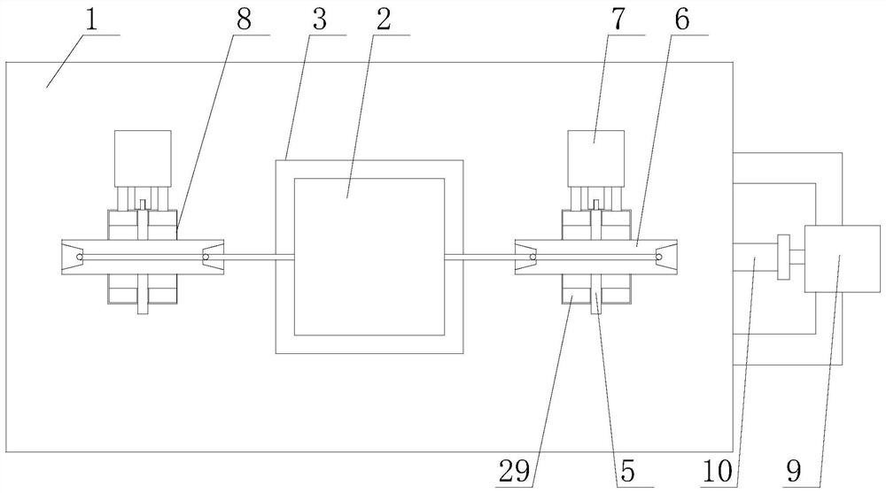
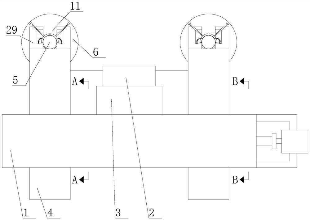
[0029] Based on the above purpose, the first aspect of the present invention proposes an embodiment of an auxiliary device for a number tube machine, such as figure 1 and figure 2 shown, including

[0030] The bottom plate 1 and the numbered pipe machine 2 fixed on the bottom plate 1 through the spacer 3 are provided with matching holes 8 on the bottom plate 1 on the inlet and outlet sides of the numbered pipe machine 2;

[0031] The moving block 4 located in the matching hole 8 and the driving part connected with the moving block 4 by power;

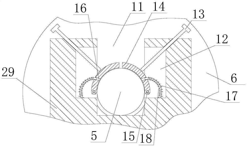
[0032] The fixed plate 29 symmetrically arranged on the upper end surface of the moving block 4, the upper end surface of the fixed plate 29 is provided with a shaft groove 11; ...