A combined energy-absorbing structure

An energy-absorbing structure and combined technology, applied in bumpers, vehicle components, vehicle safety arrangements, etc., can solve the problems of reduced energy absorption of filling structures, and achieve increased stability of deformation form and force, and increased radial bearing capacity. , reduce the effect of intrusion and damage

Active Publication Date: 2021-01-29
HARBIN INST OF TECH
View PDF6 Cites 0 Cited by
  • Summary
  • Abstract
  • Description
  • Claims
  • Application Information

AI Technical Summary

Problems solved by technology

[0005] The purpose of the present invention is to solve the problem that the existing honeycomb filled thin-walled tube structure reduces the overall energy absorption of the filled structure due to the thin-walled tube intruding into the honeycomb during compression

Method used


Image

  • A combined energy-absorbing structure
  • A combined energy-absorbing structure
  • A combined energy-absorbing structure

Examples


specific Embodiment approach 1

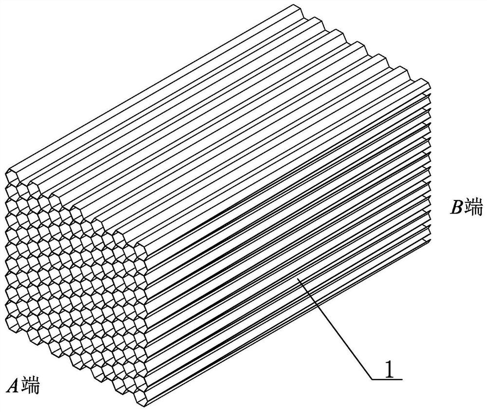
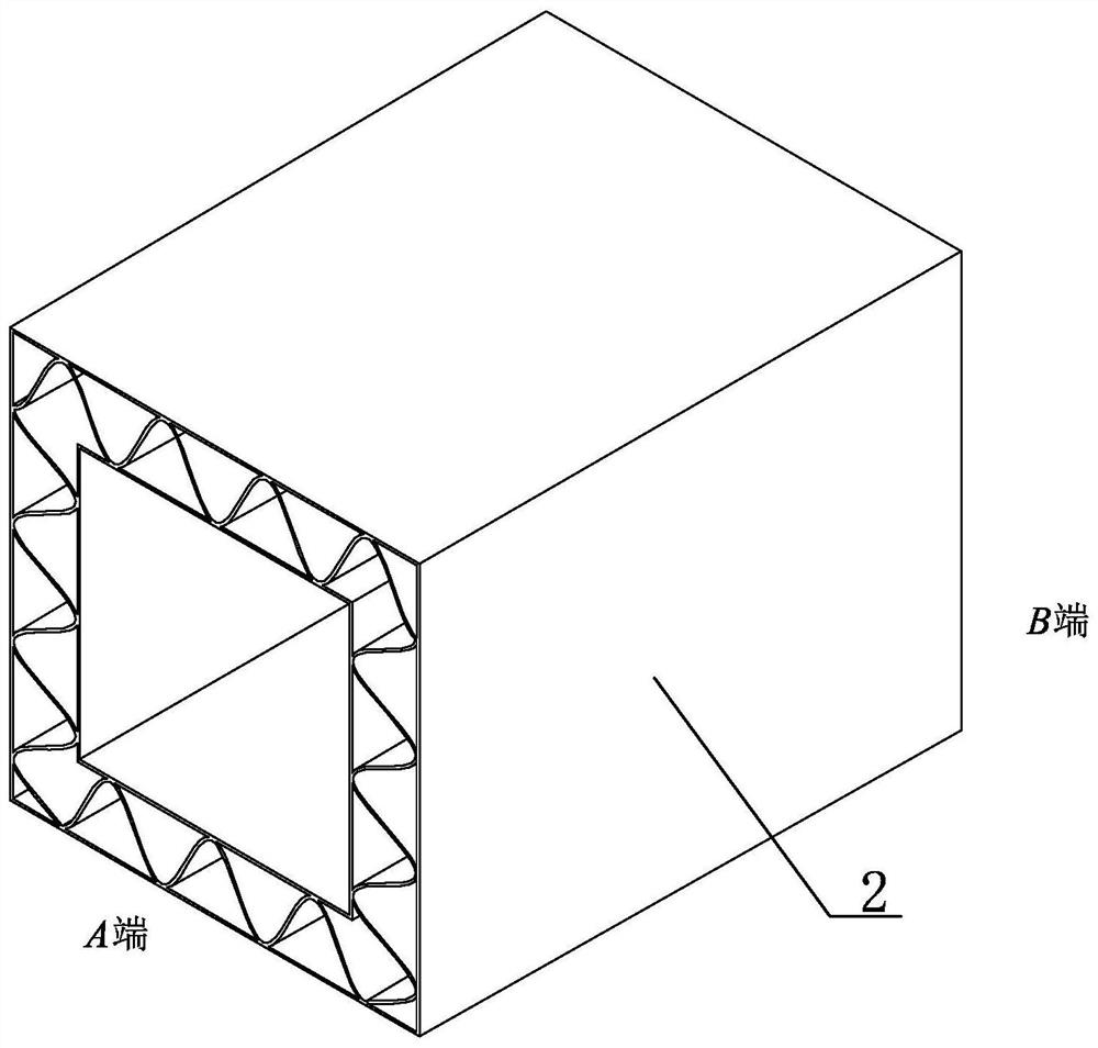
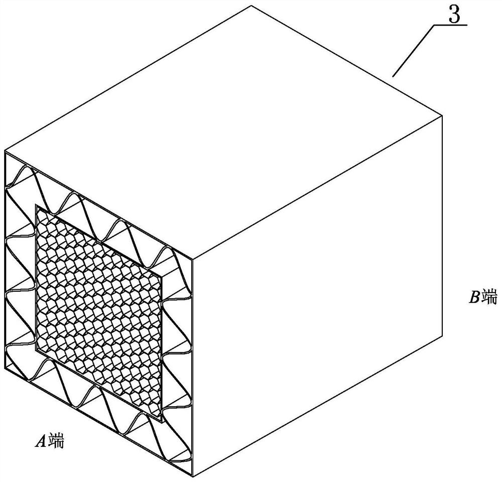
[0031] Specific implementation mode one: combine Figure 1 to Figure 4 Describe this embodiment, a combined energy-absorbing structure of this embodiment includes a buffer energy-absorbing block 1 and a porous thin-walled tube 2, the buffer energy-absorbing block 1 is a variable thickness energy-absorbing block, and the porous thin-walled tube 2 is a variable-thickness thin The wall pipe, the buffer energy-absorbing block 1 is filled into the porous thin-wall pipe 2 to form the energy-absorbing structure 3 .

[0032] The present invention adopts a porous thin-walled tube with variable thickness, and simultaneously fills the porous buffer and energy-absorbing material into the porous thin-walled tube with variable thickness;

[0033] The invention is not limited to the field of rail train energy absorption, but also can be used in other fields with buffer systems such as automobiles and aerospace.

specific Embodiment approach 2

[0034] Specific implementation mode two: combination Figure 1 to Figure 4 To describe this embodiment, the energy-absorbing block 1 of this embodiment is a honeycomb block, a foam block or a rubber block. Such a design has a wide range of applications. Other components and connections are the same as those in the first embodiment.

specific Embodiment approach 3

[0035] Specific implementation mode three: combination Figure 1 to Figure 4 The present embodiment will be described. The strength of the energy-absorbing block 1 of the present embodiment is equal strength or variable strength. Such a design can cooperate with the inner thin-walled tube 4, the outer thin-walled tube 5 and the stiffened plate 6 to adjust the buffering force of the combined structure to meet different application scenarios, such as: if the buffering force gradually increases, the buffering force is constant The buffer energy-absorbing system whose value and buffer force gradually decrease. . Other compositions and connections are the same as those in Embodiment 1 or 2.


PUM


Abstract

A combined energy-absorbing structure relates to an energy-absorbing structure. The present invention aims to solve the problem that the overall energy absorption of the filled structure is reduced due to the thin-walled tubes intruding into the honeycomb when the existing honeycomb filled thin-walled tube structure is compressed. The invention comprises a buffer energy-absorbing block (1) and a porous thin-walled tube (2), the buffering energy-absorbing block (1) is a variable-thickness energy-absorbing block, the porous thin-walled tube (2) is a variable-thickness thin-walled tube, and the buffering energy-absorbing The block (1) is filled into the porous thin-walled tube (2) to form an energy-absorbing structure (3). The buffer energy-absorbing block (1) is a honeycomb block, a foam block or a rubber block. The strength of the buffer energy-absorbing block (1) is equal strength or variable strength. The porous thin-walled pipe (2) includes an inner thin-walled pipe (4), an outer thin-walled pipe (5) and a stiffened plate (6), the inner thin-walled pipe (4) is embedded in the outer thin-walled pipe (5), A stiffened plate (6) is provided between the inner thin-walled pipe (4) and the outer thin-walled pipe (5). The invention is used in fields with buffer systems such as automobiles and aerospace.

Description

technical field [0001] The invention relates to an energy-absorbing structure, in particular to a combined energy-absorbing structure with a honeycomb-filled thin-walled structure, which belongs to the field of energy-absorbing. Background technique [0002] With the rapid development of China's high-speed rail and urban rail, convenient and efficient rail transit has become the first choice for many people, and its safety protection is very important. Buffer energy-absorbing devices in the field of rail trains mainly include honeycomb, expanding tubes, shrinking tubes, planing tubes, and thin-walled structures. The honeycomb has been widely used due to its advantages of high specific strength, large specific energy absorption, and stable buffering process. As a strictly orthotropic material, honeycomb mainly bears axial load. When the force direction deviates slightly from the axial direction, the deformation shape and energy absorption capacity of honeycomb are greatly re...

Claims


Application Information

Patent Timeline
Patent Type & Authority Patents(China)
IPC IPC(8): B61F19/04B60R19/18B60R19/22
CPCB60R19/18B60R19/22B60R2019/1866B61F19/04
Inventor 刘荣强黄江平邓宗全孙朋王晨
Owner HARBIN INST OF TECH
Why Eureka
Try Eureka