Micro-rail transit power supply system, balancing device and control method thereof
A technology of balancing device and power supply system, applied in the field of rail transit, can solve the problems of unbalanced three-phase power supply of power grid and inapplicability of micro-rail transit system, etc.
- Summary
- Abstract
- Description
- Claims
- Application Information
AI Technical Summary
Problems solved by technology
Method used
Image

Examples
Embodiment 1
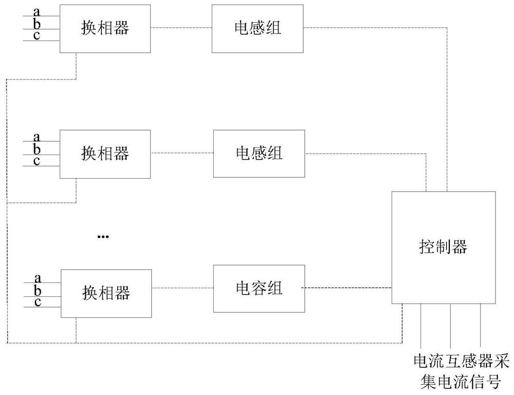
[0030] figure 1 shows the schematic structure of the balance device in the embodiment of the present application Figure 1 ,as the picture shows.
[0031] An embodiment of the present application provides a balancing device, including: a phase commutator, an inductor group, a capacitor group, and a controller. The first terminal of the phase converter is used to connect each phase of the transformer, and the second terminal is connected to the inductor group or The capacitor bank is connected, and the controller is respectively connected to the inductor bank, the capacitor bank, and the commutator;
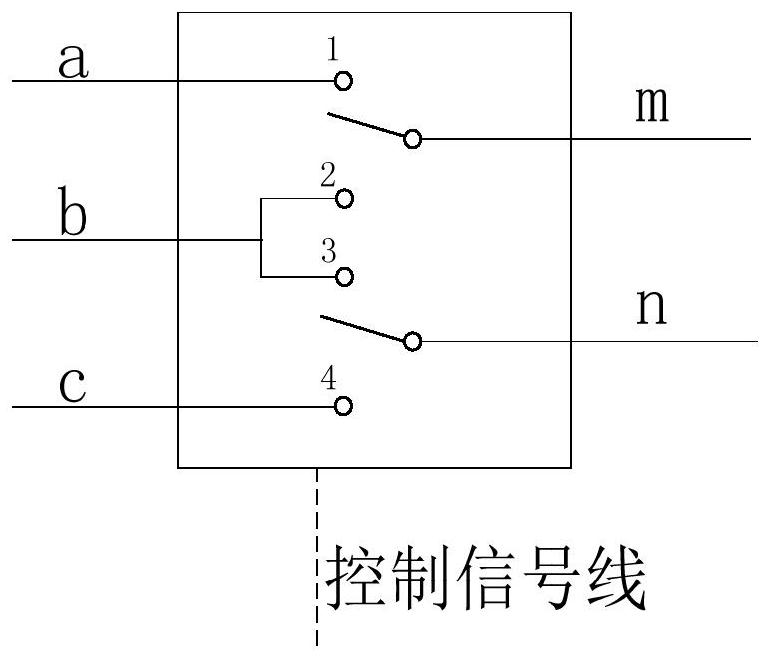
[0032] The phase commutator is used to change the phase connected to the inductance group or the capacitor group;
[0033] The controller is used to receive the current signal of each phase of the transformer, and control the inductance group or the capacitance group to change the inductance value or capacitance value according to the current signal, and control the commutation ...
Embodiment 2
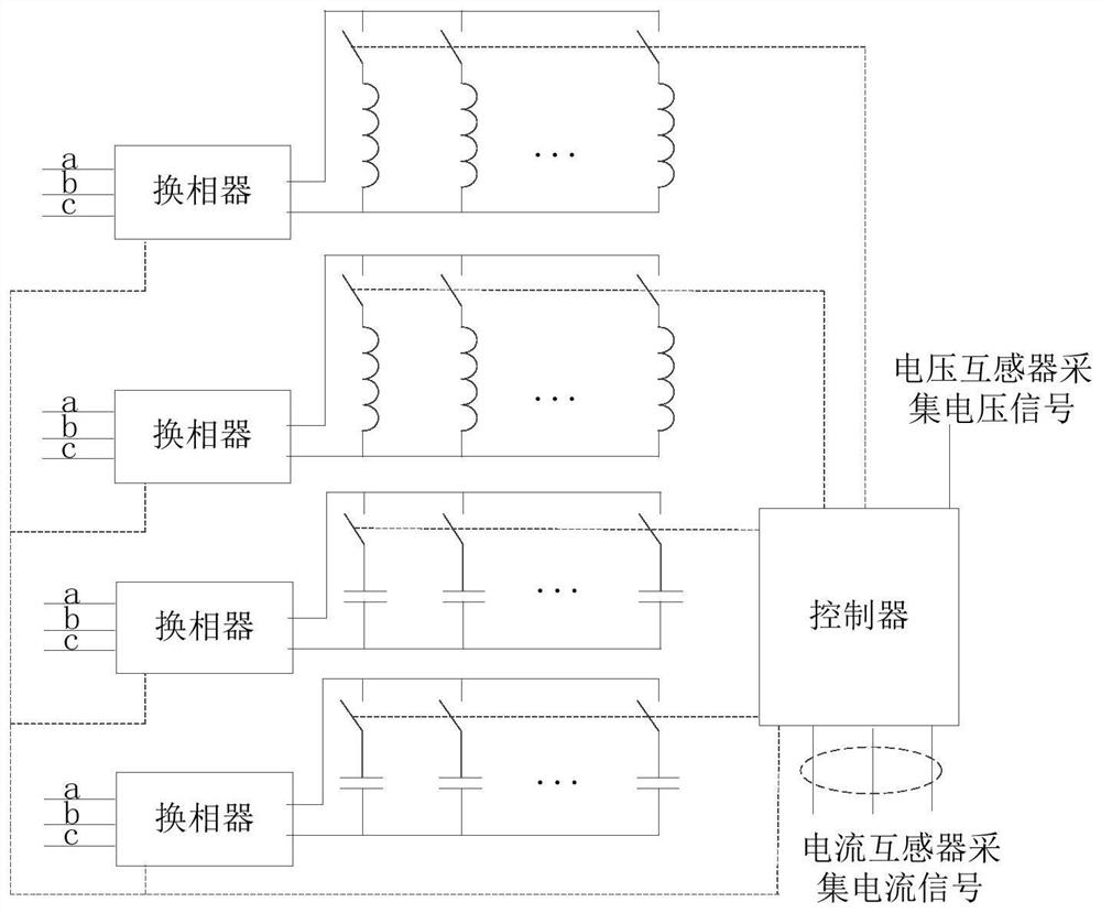
[0102] An embodiment of the present application provides a power supply system for micro-rail transit, including: a transformer, a current transformer, and the balancing device as described above; each phase of the transformer is connected to the balancing device, and one end of the current transformer is connected to the balancing device. One phase of the transformer is connected, and the other end is connected to the balance device, and the current transformer is used to collect current signals and transmit them to the balance device; each phase of the transformer is used to connect with different sections of track beam contact wires.
[0103] Figure 4 It shows the structural diagram of the micro-rail transit power supply system in the embodiment of the present application. As shown in the figure, the a-phase, b-phase and c-phase of the three-phase transformer are respectively connected to the contact wires of different sections of the track beam, and the phase-to-phase volt...
Embodiment 3
[0117] Based on the same inventive concept, this embodiment of the present application also provides a control method using the balancing device in Embodiment 1, which will be described below.
[0118] Figure 5 A schematic flow diagram of the implementation of the balance control method in the embodiment of the present application is shown. As shown in the figure, the embodiment of the present application provides a method for implementing balance control using the balance device in the above-mentioned embodiment 1, including the following steps:
[0119] Step 501, receiving the current signal of each phase of the transformer;
[0120] Step 502: Control the inductance group or the capacitance group to change the inductance value or capacitance value according to the current signal, and control the commutation of the phase converter, so as to compensate the current between the phases of the transformer.
[0121] The control method provided by the embodiment of the present app...
PUM
 Abstract
Description
Claims
Application Information
 - R&D
- Intellectual Property
- Life Sciences
- Materials
- Tech Scout
- Unparalleled Data Quality
- Higher Quality Content
- 60% Fewer Hallucinations
Browse by: Latest US Patents, China's latest patents, Technical Efficacy Thesaurus, Application Domain, Technology Topic, Popular Technical Reports.
© 2025 PatSnap. All rights reserved.Legal|Privacy policy|Modern Slavery Act Transparency Statement|Sitemap|About US| Contact US: help@patsnap.com