
Refined sampling device for soil detection
A sampling device and soil detection technology, applied in the field of soil detection, can solve the problems of single function of soil collection device, waste of manpower and time, doping with gravel and weeds, etc., to improve detection effect, reduce physical labor, and simple structure Effect
Patent Information
- Authority / Receiving Office
- CN · China
- Patent Type
- Applications(China)
- Current Assignee / Owner
- Publication Date
- 2020-06-12
- Estimated Expiration
- Not applicable · inactive patent
Smart Images
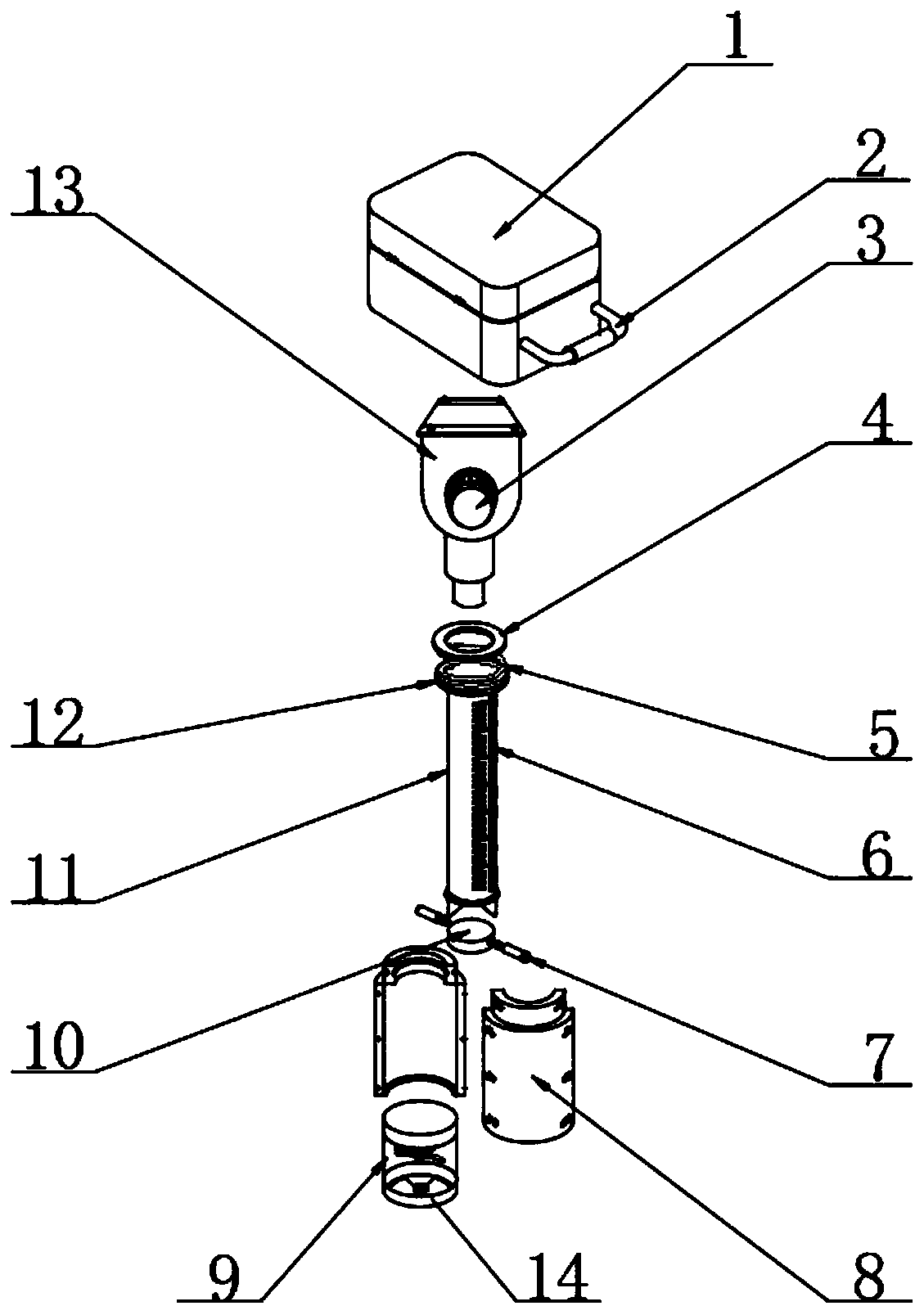
Figure 1 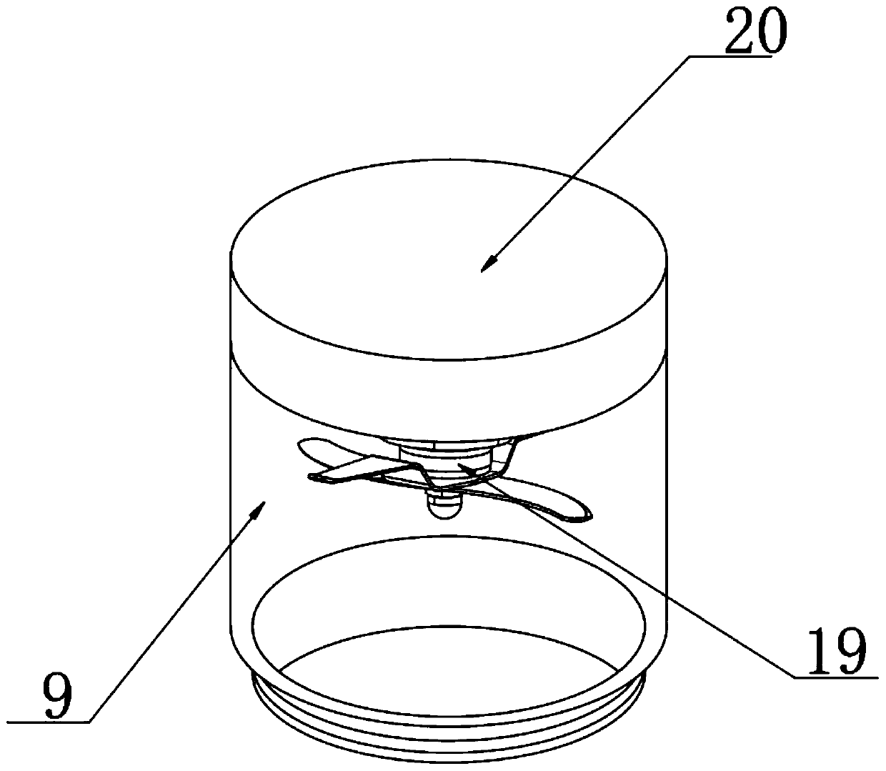
Figure 2 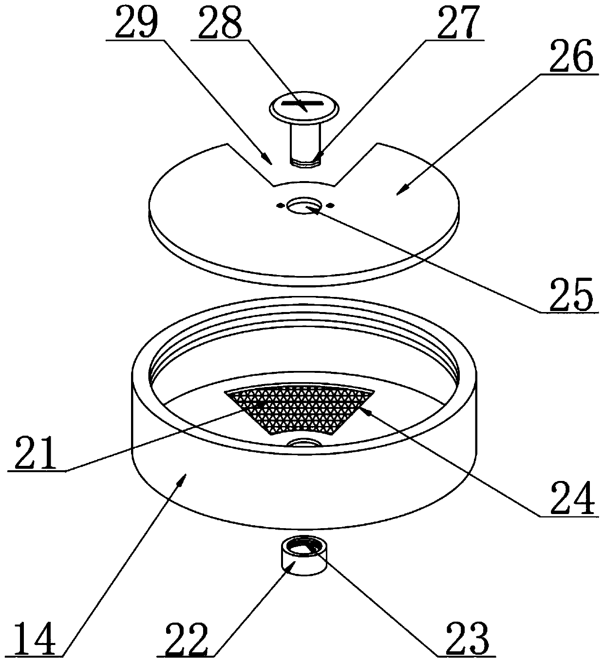
Figure 3
Abstract
Description
technical field
[0001] The invention relates to the technical field of soil detection, in particular to a refined sampling device for soil detection. Background technique
[0002] Soil environment monitoring refers to the determination of environmental quality and its change trend through the determination of representative values of factors affecting soil environmental quality. What we usually call soil monitoring refers to soil environment monitoring, which generally includes point sampling, sample preparation, and analysis methods. , result characterization, data statistics and quality evaluation and other technical contents.
[0003] However, the functions of the existing soil sampling devices are relatively simple, and the collected soil is relatively rough, and at the same time mixed with gravel and weeds, so manual processing is required before testing, which is a waste of manpower and time. In addition, some soil sampling devices on the market Equipped with a pulv...
Examples
Embodiment Construction
[0021] see Figure 1-5 , in an embodiment of the present invention, a refined sampling device for soil detection, comprising a storage box 1, handles 2 are fixed on both sides of the storage box 1, and a soil removal bar 11 is arranged below the storage box 1, and the soil removal bar The bottom end of 11 is sharp, and the storage box 1 is connected with the soil removal rod 11 through an impact structure. Distributed through grooves 6, the inside of the soil removal rod 11 is provided with a soil pressing block 10, and the outside of the soil removal rod 11 is provided with a force rod 7 at the position corresponding to the two through grooves 6, and one end of the two force rods 7 The two through grooves 6 are screwed and fixed on both sides of the pressed soil block 10 respectively. A connecting ring 4 is arranged above the force-bearing piece 12, and a spring 5 is fixed between the force-bearing piece 12 and the connecting ring 4. The impact structure includes The casing ...