A New Type of Low Power Leakage Protector

A leakage protector and low power consumption technology, which is applied to emergency protection circuit devices, emergency protection devices with automatic disconnection, electrical components, etc., can solve the problems of leakage protector temperature rise, complex circuit structure, unfavorable energy conservation and environmental protection, etc. , to achieve the effects of small internal temperature rise, simple circuit structure, and reduced project cost

Active Publication Date: 2022-06-21
格述电子技术(上海)有限公司
View PDF5 Cites 0 Cited by
  • Summary
  • Abstract
  • Description
  • Claims
  • Application Information

AI Technical Summary

Problems solved by technology

But the disadvantage is that the power consumption is relatively large, generally around 0.5 watts, which causes the internal temperature of the leakage protector to rise, and it is especially easy to overheat and damage when working in a high temperature environment
At the same time, the circuit structure of directly taking power from the mains is also more complicated and the cost is higher
If the leakage protector is always working in the distribution box, the cumulative power consumption of 0.5 watts of power consumption in a year is about four degrees, and there are at least hundreds of millions of leakage protectors in the whole country, which is not conducive to energy conservation and environmental protection.

Method used


Image

  • A New Type of Low Power Leakage Protector
  • A New Type of Low Power Leakage Protector
  • A New Type of Low Power Leakage Protector

Examples


Embodiment 1

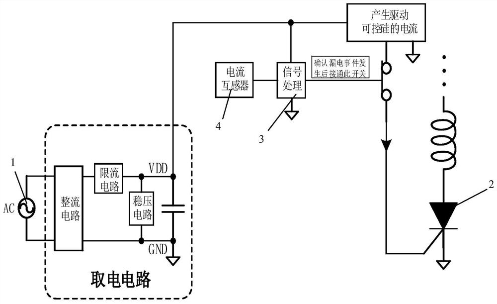
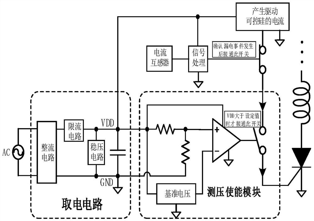
[0026] like figure 2 and image 3 Shown is a schematic diagram of the overall module of a novel low-power leakage protector of the present invention and a schematic diagram of the specific composition of the corresponding first embodiment, including an AC power supply 1, a thyristor 2, a signal processing module 3, a current transformer 4, The thyristor current driving module and the power taking circuit module, the input end of the power taking circuit module is connected with the AC power supply 1, the output end of the power taking circuit module is connected with the control end of the thyristor 2 after passing through the thyristor current driving module, The signal processing module 3 is arranged between the No. 1 enabling terminal of the thyristor current drive module and the output terminal of the power taking circuit module and is grounded. The signal processing module 3 is also connected to the output terminal of the current transformer 4. The power taking circuit m...

Embodiment 2

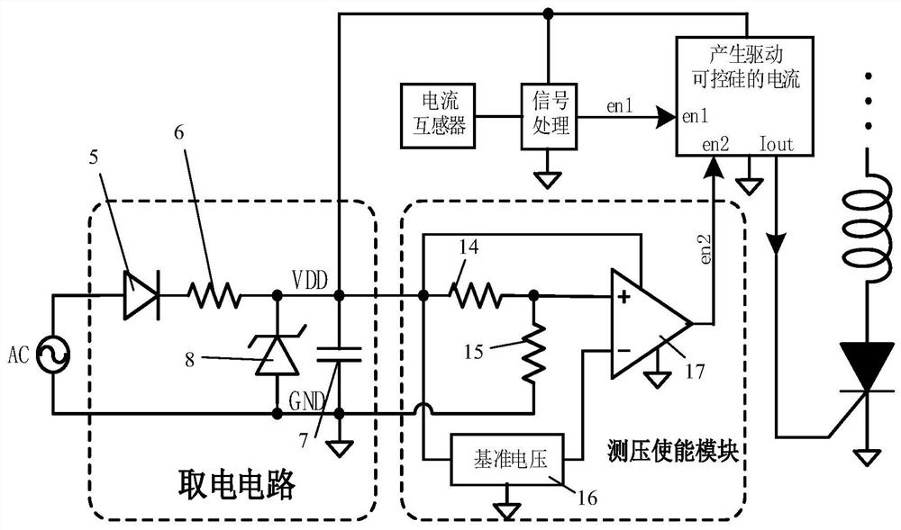
[0035] like Figure 4 Shown is the second embodiment of the present invention. It can be seen from the figure that the main part of this embodiment is the same as that of the first embodiment, mainly for the power taking circuit module and the pressure measurement enabling module as the second embodiment. different to change.

[0036] The power-taking circuit module in Embodiment 2 includes a second capacitor 9, a second resistor 10, a first full-bridge rectifier circuit 11, a second Zener diode 12, and a third capacitor 13. One end of the second capacitor 9 is connected to the AC power supply. 1 is connected to the live wire, the other end of which is connected to the AC input terminal of the first full-bridge rectifier circuit 11 after passing through the second resistor 10, and the other AC input terminal of the first full-bridge rectifier circuit 11 is connected to the neutral wire of the AC power supply 1. Both the second Zener diode 12 and the third capacitor 13 are con...


PUM


Abstract

The invention relates to a novel low-power leakage protector, which includes an AC power supply, a thyristor, a signal processing module, a current transformer, a thyristor current drive module, and a power-taking circuit module. The novel low-power leakage protector It also includes a voltage measurement enabling module, and the thyristor current drive module is also controlled by the enabling control of the voltage measurement enabling module, and the voltage measurement enabling module only monitors the output voltage of the power-taking circuit module When a certain condition is met, the current to drive the thyristor is allowed to be output, that is, only when the voltage measurement enabling module and the signal processing module both output valid enabling signals, the thyristor is allowed to drive the current The module output drives the conduction current of the thyristor. Compared with the prior art, the invention has the advantages of low driving power consumption of the thyristor, simplified structure of the power-taking circuit, low power consumption, small temperature rise, energy saving and environmental protection, and low cost.

Description

technical field [0001] The invention relates to the technical field of electrical protector switches, in particular to a novel low-power leakage protector. Background technique [0002] The principle of the scheme mainly adopted by the existing leakage protector is: when leakage occurs, the sum of the currents of all the live and neutral lines of the power supply is non-zero, and the difference can be detected by the current transformer, and then amplified, processed and confirmed by the relevant circuit. , drive the thyristor to conduct, the conducting current flows through the trip coil of the release, and the release acts to cut off the mains power supply switch. The existing mainstream leakage protector scheme is based on an application-specific integrated circuit chip to process the signal output by the current transformer and drive the thyristor to conduct. [0003] The advantage of this scheme is that the signal processing is accurate, and it can reliably drive the t...

Claims


Application Information

Patent Timeline
Patent Type & Authority Patents(China)
IPC IPC(8): H02H3/32
CPCH02H3/325
Inventor 何波
Owner 格述电子技术(上海)有限公司
Why Eureka
Try Eureka