A combined silage coating machine and its application method

A technology of silage and coating machine, which is applied in the field of coating equipment, can solve the problems of inconvenience, poor quality and low coating efficiency, and achieve the effects of good coating quality, convenient use and convenient coating.

Active Publication Date: 2022-01-11
朱德文
View PDF3 Cites 0 Cited by
  • Summary
  • Abstract
  • Description
  • Claims
  • Application Information

AI Technical Summary

Problems solved by technology

[0004] The purpose of the present invention is to solve the shortcomings of more inconvenience, low coating efficiency and poor quality in the prior art, and propose a combined silage coating machine

Method used


Image

  • A combined silage coating machine and its application method
  • A combined silage coating machine and its application method
  • A combined silage coating machine and its application method

Examples


Embodiment 1

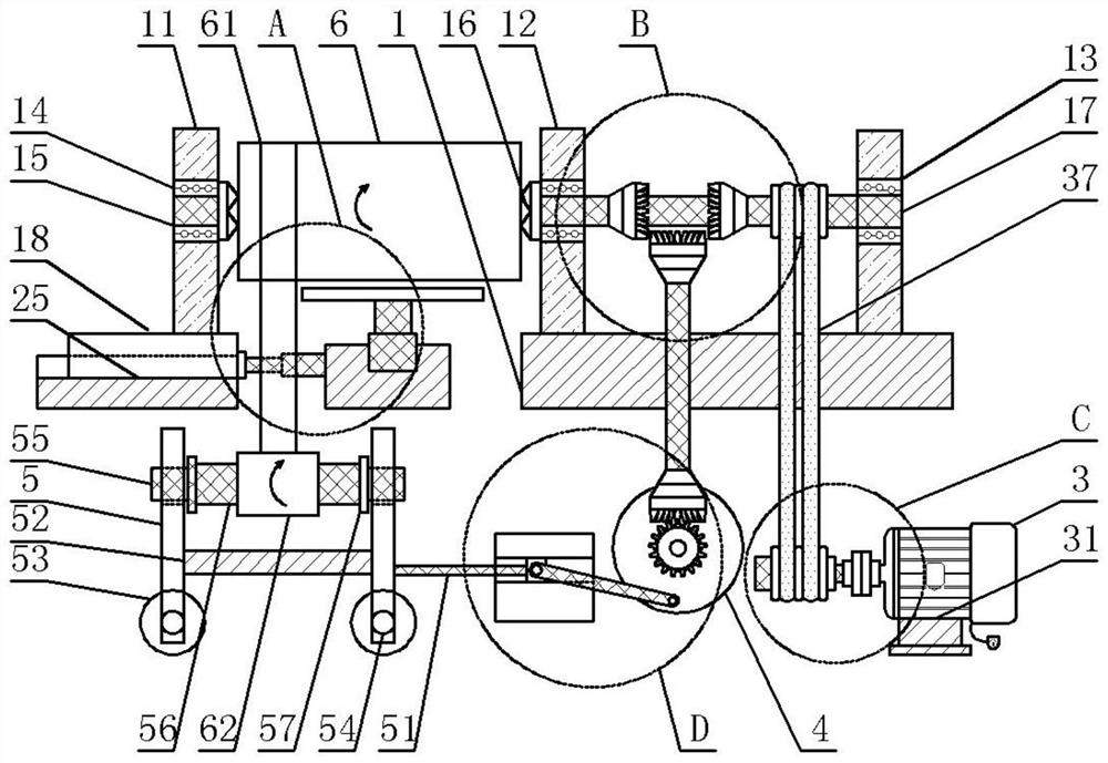
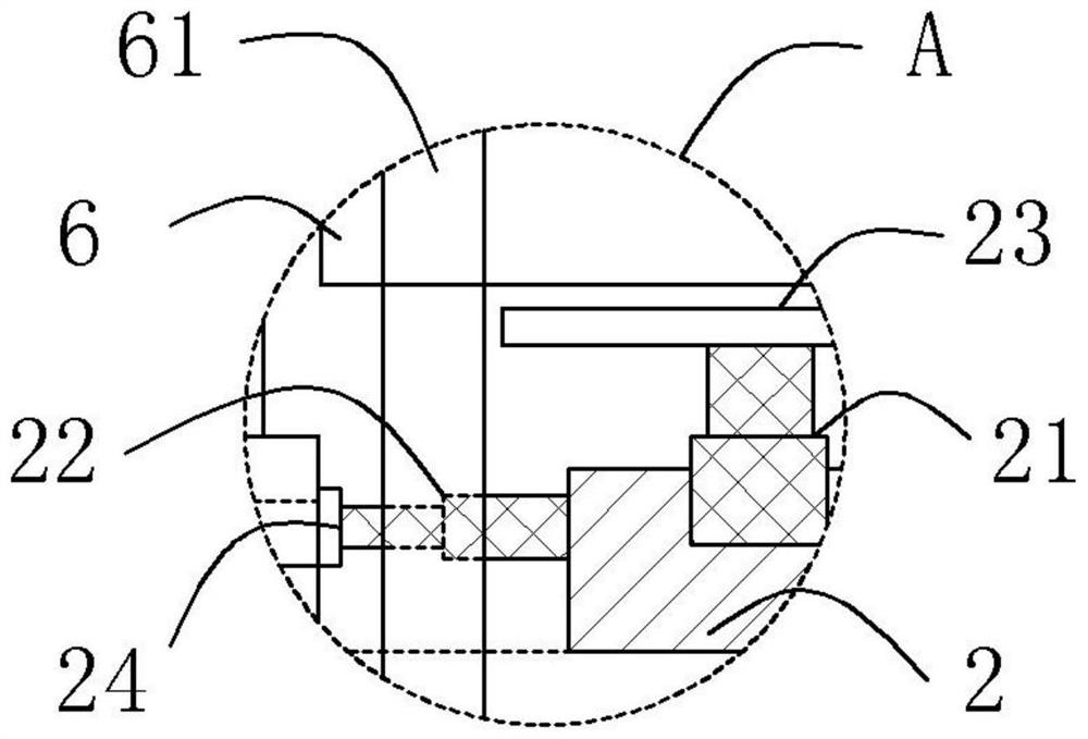
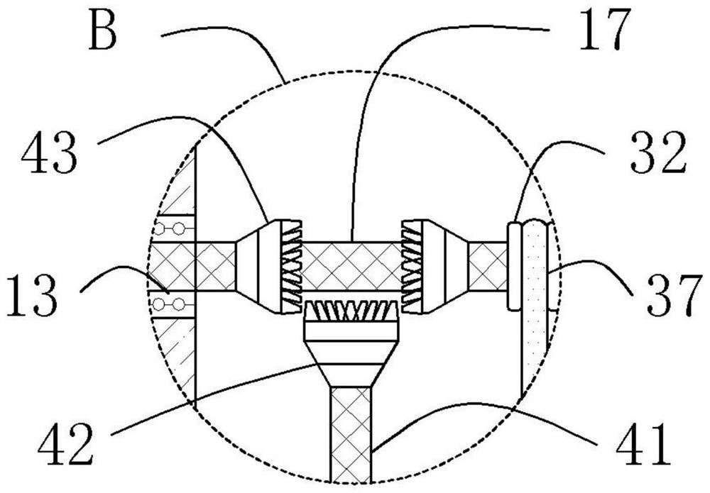
[0036] Embodiment 1: In order to realize the bale coating operation of different shapes and the purpose of good coating quality and high efficiency, this embodiment provides a combined silage coating machine, see Figure 1-Figure 7 , including a base plate 1, a telescopic mechanism, a belt transmission mechanism, a connecting rod assembly, and a moving part. The base plate 1 is a rectangular plate placed horizontally, and a pair of vertical plates 12 are longitudinally arranged on the top surface of the base plate 1. The center positions are all horizontally recessed with first bearing grooves, and first bearings 13 are arranged in the first bearing grooves, and a horizontal shaft 17 that runs through both ends is arranged in the two first bearings 13; the left side of the bottom plate 1 A telescopic mechanism is provided on the side ground, and the telescopic mechanism contains a hydraulic vertical cylinder 21 and a hydraulic horizontal cylinder 22. The top of the hydraulic ve...

Embodiment 2

[0046] Embodiment 2: In this embodiment, a method for using a combined silage coating machine is specifically provided, including the following steps:

[0047] Step 1, the first power line, the second power line, and the third power line are respectively electrically connected to the external power supply, and the hydraulic cylinder and the motor are connected to an external control switch, and the vertical movement of the telescopic rod of the hydraulic vertical cylinder 21 and the hydraulic pressure are controlled by the control switch. The lateral movement of the telescopic rod of the horizontal cylinder 22 and the rotation of the motor 3;

[0048] Step 2, place the bale 6 horizontally on the support plate 23, control the hydraulic vertical cylinder 21 telescopic rod to rise, so that the center of the right side of the bale 6 on the support plate 23 is aligned with the gripper at the center of the left side of the vertical plate 12 16. At the same time, control the stretchi...


PUM


Abstract

The invention discloses a combined silage coating machine and its use method, which comprises a bottom plate, a telescopic mechanism, a belt transmission mechanism, a connecting rod assembly, and a moving part. Axis; the left side of the bottom plate is equipped with a telescopic mechanism, the left end of the hydraulic horizontal cylinder in the telescopic mechanism is connected with a sliding piece, and the top surface of the sliding plate on the sliding piece is provided with a bracket plate; the horizontal axis rotates synchronously with the driving shaft on the belt transmission mechanism through the transmission belt , the upper part of the left section of the horizontal axis is provided with a pair of bevel gears, and the bottom of the pair of bevel gears is engaged with the first bevel gear on the connecting rod assembly; the connecting rod assembly is fixedly connected with the moving part, and the roller on the moving part is sleeved With film sleeve. The invention is more convenient and fast for film introduction and coating, can adapt to various shapes of straw bales, has high quality of coating, and can realize the coating operation of straw bales of various shapes.

Description

technical field [0001] The invention relates to the technical field of coating equipment, in particular to a combined silage coating machine and a use method thereof. Background technique [0002] Coated silage is the main way of silage. Coating technology and equipment are widely used in various straw and pasture packaging silage coating operations. The existing straw bale coating machines include square bales and round bales. [0003] In the existing wrapping methods, most of the straw bales change their motion patterns to cater to the membrane to achieve the overall wrapping. The straw bale is equivalent to active movement, and the wrapping membrane body is a follow-up movement; this wrapping method leads to low wrapping efficiency. The priming film is inconvenient, inconvenient to use, and has poor adaptability to bales of different shapes, resulting in low quality of the film. Contents of the invention [0004] The purpose of the present invention is to propose a com...

Claims


Application Information

Patent Timeline
Patent Type & Authority Patents(China)
IPC IPC(8): A01F15/07
CPCA01F15/071
Inventor 朱德文
Owner 朱德文
Why Eureka
Try Eureka