Cogeneration unit heat supply method and heat supply system

A combined heat and power unit and unit technology, applied to heating systems, hot water central heating systems, and central heating, can solve the problem that the loss of low-pressure cylinder exhaust cold source cannot be fully utilized, etc.

Active Publication Date: 2020-07-03
GUODIAN LONGYUAN ENERGY SAVING TECH
View PDF6 Cites 5 Cited by
  • Summary
  • Abstract
  • Description
  • Claims
  • Application Information

AI Technical Summary

Problems solved by technology

[0004] In view of the large contradiction between heat load demand and electric load peak shaving of cogeneration units during the heating period, when traditional steam extraction heating units use medium-pressure cylinder extraction for heating, there is a loss of low-pressure cylinder exhaust steam cold source that cannot be fully utilized Shortcomings
This poses a greater challenge to how to improve the flexibility of unit load peak regulation during the heating period of the unit and the heating economy of the unit

Method used


Image

  • Cogeneration unit heat supply method and heat supply system
  • Cogeneration unit heat supply method and heat supply system
  • Cogeneration unit heat supply method and heat supply system

Examples


Embodiment 1

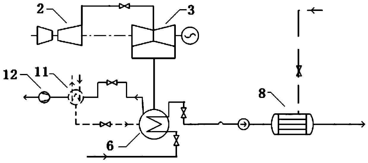
[0030] refer to figure 1 , this embodiment provides a heat supply system for cogeneration units, figure 1 The steam turbine regenerative extraction system and the condensing / feeding water system are omitted in the paper, and the heating system also omits other auxiliary equipment, and only the main equipment is systematically described. The heating system mainly includes high pressure cylinder 1, medium pressure cylinder 2, low pressure cylinder 3, generator 4, cooling tower 5, condenser 6, heat network return pump 7, heat network heater 8, heat storage device 9, auxiliary Vacuumizing device 10, steam cooler 11, vacuum pump 12 and controller. Because the cooling tower 5 is adopted, the heat supply system of this embodiment is suitable for wet cooling units and indirect air cooling units.

[0031] The exhaust port of the high-pressure cylinder 1 communicates with the steam inlet of the medium-pressure cylinder 2 .

[0032] The exhaust port of the medium-pressure cylinder 2 a...

Embodiment 2

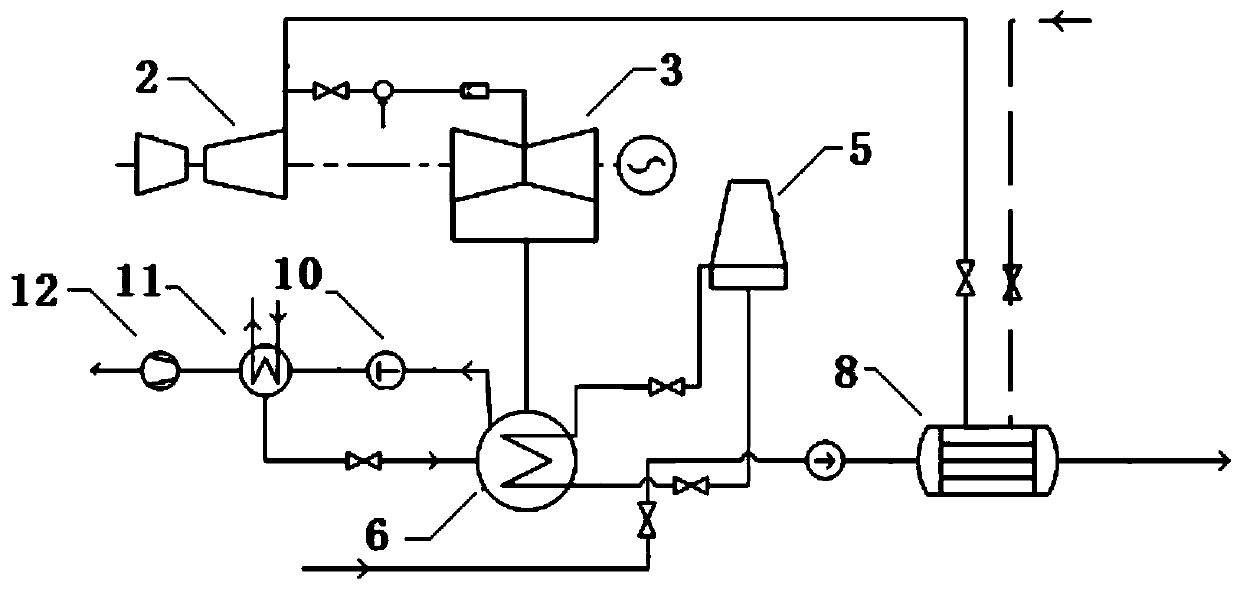
[0100] refer to Figure 8 , this embodiment provides a heat supply system for cogeneration units, Figure 8 The steam turbine regenerative extraction system and the condensing / feeding water system are omitted in the paper, and the heating system also omits other auxiliary equipment, and only the main equipment is systematically described. The heating system mainly includes high-pressure cylinder 1, medium-pressure cylinder 2, low-pressure cylinder 3, generator 4, condenser 6, heat network return pump 7, heat network heater 8, heat storage device 9, and auxiliary vacuum device 10 , steam cooler 11, vacuum pump 12, air-cooled island 33, exhaust device 34 and controller. Because the air cooling island 33 is used, the heating system of this embodiment is suitable for direct air cooling units.

[0101]The exhaust port of the high-pressure cylinder 1 communicates with the steam inlet of the medium-pressure cylinder 2 .

[0102] The exhaust port of the medium-pressure cylinder 2 a...


PUM


Abstract

The invention relates to the technical field of steam turbine generator units, and particularly provides a cogeneration unit heat supply method and heat supply system which solve the contradiction that the heat load demand and the electrical load peak regulation are difficult to schedule simultaneously in the heat supply period. According to the heat supply method and system, a high-back-pressureheat storage mode can be adopted when the heat load demand is low and the electrical load demand is high, a high-back-pressure heat release mode is adopted when the heat load demand and the electricalload demand are high and the heat load demand is higher than the heat production amount matched with the electricity production amount produced according to the electrical load demand by the unit, alow-pressure cylinder near-zero output heat storage mode is adopted when the electrical load demand and the heat load demand are low, and a low-pressure cylinder near-zero output heat release mode isadopted when the electrical load demand is low, the heat load demand is high and the heat load demand is higher than the heat production amount matched with the electricity production amount producedaccording to the electrical load demand by the unit.

Description

technical field [0001] The invention relates to the technical field of steam turbine generator sets, in particular to a heat supply method and a heat supply system for a cogeneration unit. Background technique [0002] In my country's "Three North" region, due to the high proportion of coal-fired heat and power, the construction conditions of peak-shaving power supply are insufficient, and the unit has to undertake the task of heating in winter, and it is difficult to adjust the peak load of the unit during the winter heating period, resulting in a serious problem of wind power curtailment in the power grid. As an important industry in urbanization construction, combined heat and power units have played a vital role in controlling environmental pollution instead of shutting down small coal-fired heating boilers. However, in conventional combined heat and power units, the exhaust steam of the medium-pressure cylinder of the steam turbine is usually used to heat the return wat...

Claims


Application Information

Patent Timeline
Patent Type & Authority Applications(China)
IPC IPC(8): F24D3/10F24D11/00F24D19/10F01K13/00F01K11/02F01K17/02
CPCF01K11/02F01K13/00F01K17/02F24D3/1058F24D11/002F24D19/1009Y02E20/14
Inventor 杨涛钟震白旭东郝亚珍那小桃韩云峰佟增军王建勋徐磊秦万阔梁双荣杨晋宁张明远
Owner GUODIAN LONGYUAN ENERGY SAVING TECH
Why Eureka
Try Eureka