Novel roller way transmission structure of solar cell roller way furnace

A technology of solar cells and transmission structures, which is applied in circuits, photovoltaic power generation, electrical components, etc., and can solve problems such as rear-end collision of cells, affecting the sintering effect of cells 5, and the effect of irradiation

Pending Publication Date: 2020-07-07
BEIJING SOLARRAY TECHNOIOGY CO LTD +2
View PDF0 Cites 4 Cited by
  • Summary
  • Abstract
  • Description
  • Claims
  • Application Information

AI Technical Summary

Problems solved by technology

It has the following problems: as Figure 5 As shown, the entire roller table 3 passes through the furnace of the sintering furnace transversely. The furnace is divided into an upper furnace 6 and a lower furnace 8. Heating lamps 7 are arranged in the upper and lower furnaces. During the transmission process, since the roller table 3 has a shielding effect on the radiation from the lamp tube below, it will affect the sintering effect on the back of the battery sheet 5, especially the sintering of the double-sided battery, which will have a greater impact
The existing roller table irradiation furnace also uses the entire roller table to pass through the furnace horizontally, because the roller table 3 has a blocking effect on the LED light source from below. When dealing with double-sided cells, the irradiation effect will be greatly affected
In addition, with the existing roller conveying method, when the battery sheet is skewed or fragmented during the transmission process, if it cannot fall into the lower furnace in time, it will lead to rear-end collision of the battery sheet or a stacking accident

Method used


Image

  • Novel roller way transmission structure of solar cell roller way furnace
  • Novel roller way transmission structure of solar cell roller way furnace
  • Novel roller way transmission structure of solar cell roller way furnace

Examples


Embodiment Construction

[0027] The present invention will be further described below in conjunction with embodiment:

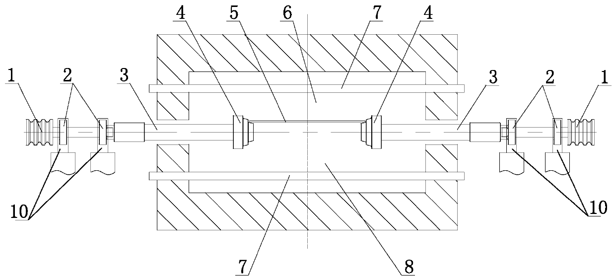
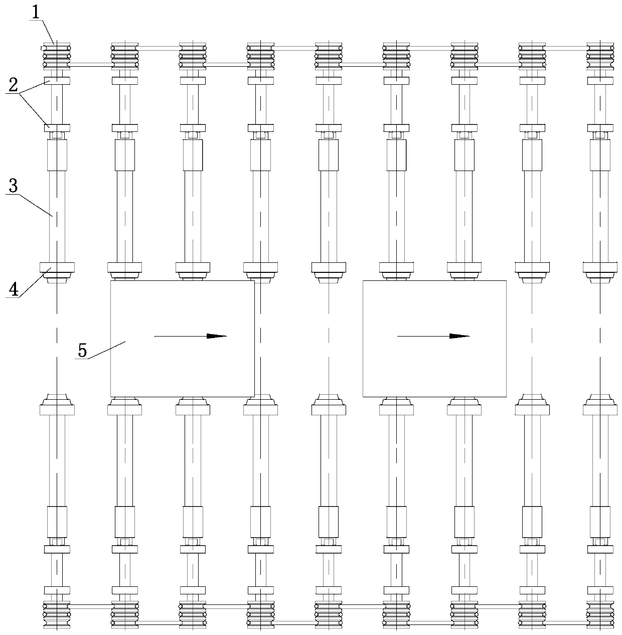
[0028] Such as Figure 1~4 As shown, in the novel roller conveyor structure of the solar battery roller furnace according to the present invention, a number of roller conveyors 3 are arranged in the furnace body, and the roller conveyors 3 are arranged on both sides of the furnace body, and intervals are provided between the roller conveyors 3 on both sides. The size of the interval matches the size of the battery sheet 5 .

[0029] Wherein, each roller table 3 is supported by two bearings 2, the bearings 2 are fixed on the bearing support base 10, the bearing support base 10 can be arranged on the slide rail, the bearing support base 10 can be adjusted left and right and fixed, by adjusting the bearing support The position of the seat 10 is used to adjust the size of the gap to match the size of the battery sheet 5 .

[0030] In this embodiment, the roller tables 3 are arranged sy...


PUM


Abstract

The invention belongs to the technical field of photovoltaic solar cells, and particularly relates to a novel roller way transmission structure of a solar cell roller way furnace. A plurality of roller ways are arranged in a furnace body, the roller ways are arranged on two sides of the furnace body, a gap is arranged between the roller ways on two sides, and the size of the gap is matched with the size of a battery piece. The novel roller way transmission structure of the solar cell roller way furnace is reasonable in design, eliminates the shielding effect of an original roller way on radiation of a heating lamp tube or an LED light source from the lower portion, improves the sintering or irradiation effect of the back face of a cell piece, eliminates the sintering or irradiation difference of the front face and the back face, and therefore, the product quality is integrally improved. Furthermore, when the battery pieces incline or are broken in the conveying process, the battery pieces can fall into the lower hearth from the intervals in time, and rear-end collision or lamination accidents of the battery pieces are prevented.

Description

technical field [0001] The invention relates to a novel roller table transmission structure of a solar cell roller furnace, belonging to the technical field of photovoltaic solar cells. Background technique [0002] In the production process of solar cells, especially crystalline silicon cells, it is necessary to use a sintering furnace to sinter the printed cells to dry the paste printed on the surface of the silicon wafer and burn off the organic solvent volatilized from the paste. , the front and back sides of the solar cell are sintered simultaneously, so that the metal electrode printed on the silicon wafer in the paste and the silicon wafer form a good ohmic contact; the sintered solar cell often needs to be irradiated by a radiation furnace treatment to improve the conversion efficiency of solar cells or to suppress the degradation of cell efficiency. Roller-type solar cell sintering furnace and irradiation furnace use roller instead of stainless steel mesh belt to t...

Claims


Application Information

Patent Timeline
Patent Type & Authority Applications(China)
IPC IPC(8): H01L21/677H01L31/18
CPCH01L21/67706H01L21/67736H01L31/186H01L31/1876Y02E10/50Y02P70/50
Inventor 袁向东曹程鹏黄英明张文袁瑒路博
Owner BEIJING SOLARRAY TECHNOIOGY CO LTD
Why Eureka
Try Eureka