AI technical title is built by Patsnap AI team. It summarizes the technical point description of the patent document.
A measuring device and ditch depth technology, which is applied in the field of field measurement, can solve the problems of inconvenient measurement of deep ditch and steep slopes, and achieve the effect of improving personal safety
Pending Publication Date: 2020-07-14
XIAN CHANGQING TECH ENG +1
View PDF0 Cites 0 Cited by
Summary
Abstract
Description
Claims
Application Information
AI Technical Summary
This helps you quickly interpret patents by identifying the three key elements:
Problems solved by technology
Method used
Benefits of technology
Problems solved by technology
[0004] The application provides a device for measuring the depth of trenches, which solves the problem of inconvenient measurement of deep trenches and steep slopes in the prior art, increases the measurement accuracy of deep trenches and steep slopes, and improves the personal safety of field workers
Method used
Image
Click on the blue label to locate the original text in one second.
Reading with bidirectional positioning of images and text.
Examples
Embodiment 1
[0033] Referring to Figures 1-2, it is a schematic structural diagram of Embodiment 1 of the present invention, a device for measuring the depth of a trench, including a control unit, and also includes:
[0035] a support part, the support part is detachably connected to the top of the chassis;
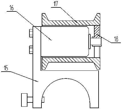
[0036] a winding part, the winding part is detachably connected to one end of the supporting part;
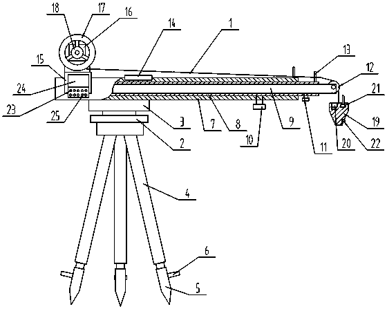
[0037] A measuring line 1, one end of the measuring line 1 is wound on the winding part, and the other end is hung on the other end of the supporting part;
[0038] Hanging and sinking part, the hanging and sinking part is fixed at the other end of the measuring line 1.
[0039] In actual use: erect the supporting part on one side of the ditch through the chassis, so that one end of the supporting part is located above the ditch, and then control the winding part to release the measuring line 1 through the control unit. Under the action of gravity, the measurement ...
Embodiment 2
[0041] On the basis of Embodiment 1, referring to Fig. 1, the difference of this embodiment is that the base frame includes a top seat 2, a turntable 3 and a tripod 4, and the supporting part is detachably connected to the upper surface of the turntable 3, so The lower surface of the turntable 3 is rotatably connected to the upper surface of the top base 2, and the top base 2 is detachably connected to the tripod 4.
[0042] In actual use: first set up the tripod 4 on one side of the ditch, connect the top base 2 to the top of the tripod 4, then connect the support part to the turntable 3, after the support part is deployed, rotate the support part, and the support part passes through the turntable 3 Rotate on the top seat 2, so that one end of the support part moves above the bottom of the ditch.
Embodiment 3
[0044] On the basis of Embodiment 2, referring to FIG. 1 , the difference of this embodiment is that: each leg of the tripod 4 is fixed with a pin 5 , and a pedal 6 is fixed on the pin 5 .
[0045] In actual use: fix the pin 5 on the legs of the tripod 4, then place the tripod 4 on one side of the ditch through the pin 5, and then step on the pedal 6 to insert the pin 5 into the ground to increase the stability of the tripod 4. When the tripod 4 is tilted, it is leveled by adjusting the length of the telescopic legs in the tripod 4 .
PUM
Abstract
The invention relates to the field of field measurement, in particular to a trench depth measuring device and method. The trench depth measuring device comprises a control unit, a bottom frame, a supporting part, a winding part, a measuring line and a hanging sinking part. The supporting part is detachably connected to the top end of the bottom frame; the winding part is detachably connected to one end of the supporting part; one end of the measuring line is wound on the winding part, and the other end of the measuring line is hung at the other end of the supporting part; the hanging sinking part is fixed at the other end of the measuring line. Due to the fact that the first sleeve, the second sleeve and the extension rod are adopted, the problem that a worker needs to enter the bottom ofa ditch for measurement is effectively solved, and then measurement can be conducted on the side wall of the ditch. Due to the adoption of the camera, a worker can know whether a measured plumb bob reaches the bottom of a trench or not and can assist in referring to and adjusting whether the position of a measuring point is accurate or not,; due to the adoption of the stepping motor, the pay-off length is controlled through stepping angle control of the stepping motor during line pay-off of a measuring line.
Description
technical field [0001] The invention relates to the field of field measurement, in particular to a ditch depth measurement device and a method thereof. Background technique [0002] During oil and gas field lineengineering survey, it is necessary to accurately survey and draw the cross-section data along the centerline direction, and draw longitudinal section diagrams based on the cross-section data in the later stage for oil and gas design. When measuring cross-sections in mountainous areas, deep ditches and steep slopes are often encountered. The depth is usually between 3 and 100 meters. There are the following two problems: 1. There are potential safety hazards in the operation. The mountains are large and deep enough to work in mountainous areas, especially in the LoessPlateau, where the soil is soft and slippery. It is very risky for operators to carry instruments and operate alone, and the safety hazards are prominent. 2. GNSS RTK is usually used for measurement i...
Claims
Application Information
Patent Timeline
Application Date:The date an application was filed.
Publication Date:The date a patent or application was officially published.
First Publication Date:The earliest publication date of a patent with the same application number.
Issue Date:Publication date of the patent grant document.
PCT Entry Date:The Entry date of PCT National Phase.
Estimated Expiry Date:The statutory expiry date of a patent right according to the Patent Law, and it is the longest term of protection that the patent right can achieve without the termination of the patent right due to other reasons(Term extension factor has been taken into account ).
Invalid Date:Actual expiry date is based on effective date or publication date of legal transaction data of invalid patent.

