
Detachable high-temperature oil pump bracket
An oil pump and high temperature technology, which is applied in the field of high temperature oil pump bracket structure improvement, can solve the problems of cumbersome process, large bracket part, inconvenient transportation, etc., so as to improve work efficiency, shorten installation and disassembly time, simplify installation and The effect of the disassembly step
- Summary
- Abstract
- Description
- Claims
- Application Information
AI Technical Summary
Problems solved by technology
Method used
Image

Examples
Embodiment 1
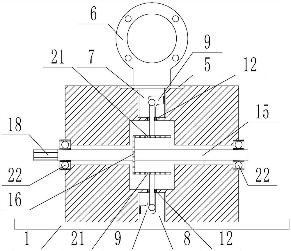
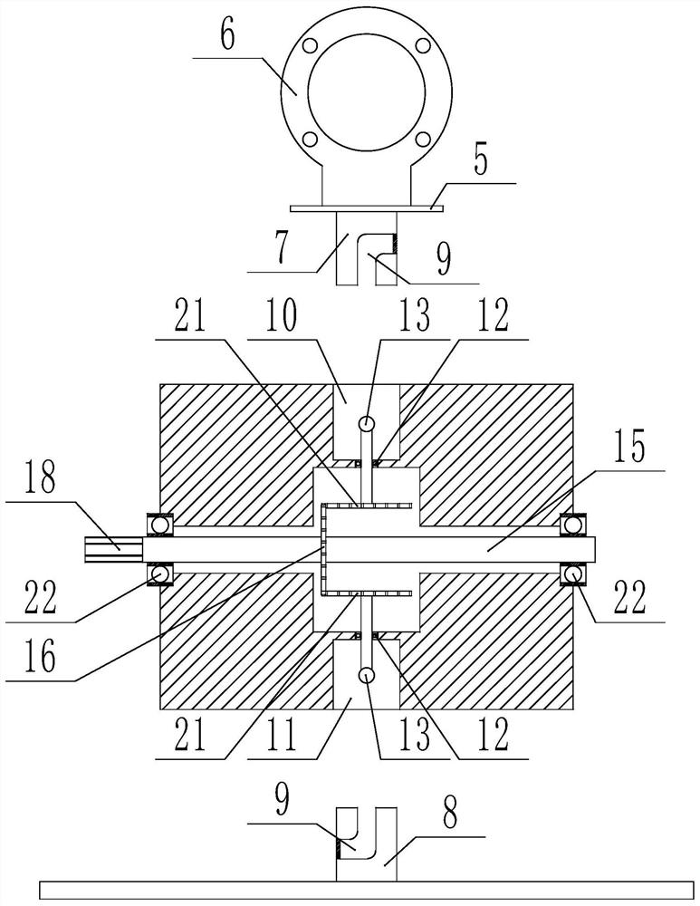
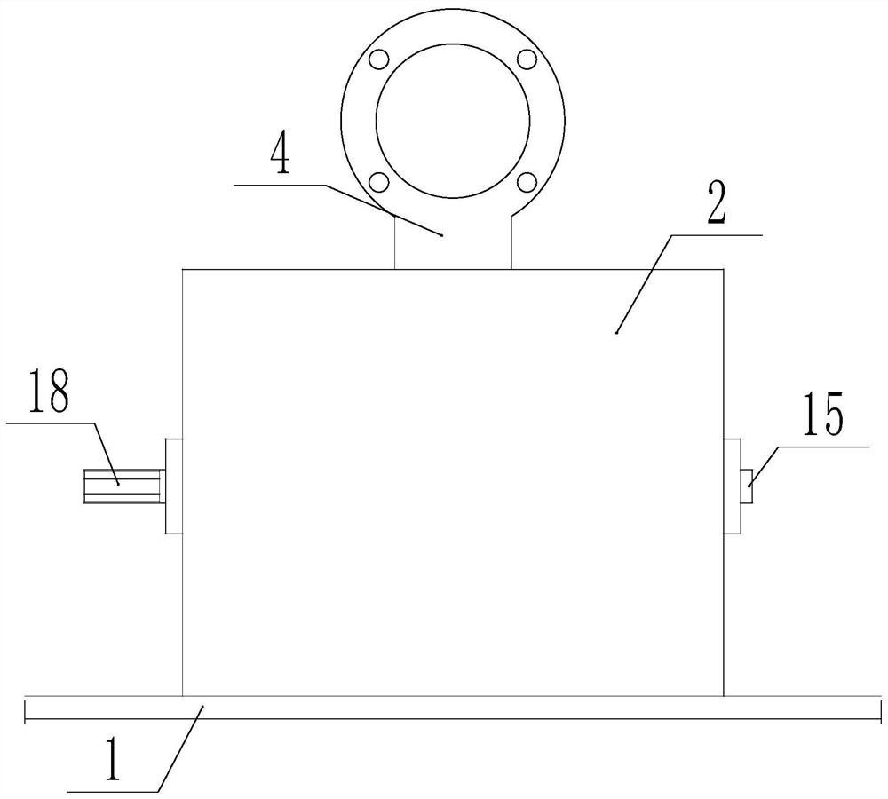
[0039] The present invention is specifically described below in conjunction with accompanying drawing, as Figure 1-11 As shown, a detachable high-temperature oil pump bracket includes a fixed plate 1, an installation body 2 is installed on the fixed plate, and a placement frame 4 is installed on the installation body, and the placement frame is used for installing a high-temperature oil pump. The placement frame includes a movable plate 5, the upper surface of the movable plate is provided with a mounting ring 6, the lower surface of the movable plate is provided with a connecting pipe 7, and the movable plate, the mounting ring and the connecting pipe are integrally structured, the technical solution The invention point is that a mounting ring 6 is provided on the upper surface of the movable plate of the placement rack, and a connecting pipe 7 is provided on the lower surface of the movable plate, and the movable plate, the mounting ring and the connecting pipe are integrall...
Embodiment 2
[0048] A bevel gear is installed on the drive shaft to replace the driving plate, and a bevel gear is installed at one end of the T-shaped bar to replace the driven plate. The bevel gear on the drive shaft meshes with the bevel gears on the two T-bars respectively. Others are the same as in Example 1.
[0049] Because the price of the bevel gear is higher than the driving plate and the driven plate used in embodiment 1, and the processing industry of the bevel gear is also far more complicated than the driving plate and the driven plate, so the preferred embodiment 1 is used in this application. The active plate and the driven plate, but the meshing effect of the active plate and the driven plate and the mutual meshing of the bevel gear are the same.
Embodiment 3
[0051] Remove the fixing plate, set the fixing groove on the fixing plate and the connecting pipe 2 on the base, the connecting pipe 2 is located in the center of the fixing groove, and then install the installation body directly in the fixing groove on the base, with the connecting pipe 2 facing upwards Insert in connection groove two, one end of the T-shaped bar cross bar in the connection groove two is inserted in the L-shaped slot of the connection pipe two. Others are the same as in Example 1.
PUM
 Abstract
Description
Claims
Application Information