Casting sand box turnover machine

A box turning machine and sand box technology, which is applied in foundry equipment, manufacturing tools, and smoke removal, etc., can solve the problems of inability to separate molding sand and castings well, and large dust from pouring sand.

Pending Publication Date: 2020-10-30
ZHENGZHOU YUSHENG CASTING CO LTD
View PDF1 Cites 3 Cited by
  • Summary
  • Abstract
  • Description
  • Claims
  • Application Information

AI Technical Summary

Problems solved by technology

[0005] In order to solve the problem that the traditional sand pouring has a lot of dust and cannot separate the molding sand from the casting well, the present invention provid

Method used


Image

  • Casting sand box turnover machine
  • Casting sand box turnover machine
  • Casting sand box turnover machine

Examples


Embodiment 1

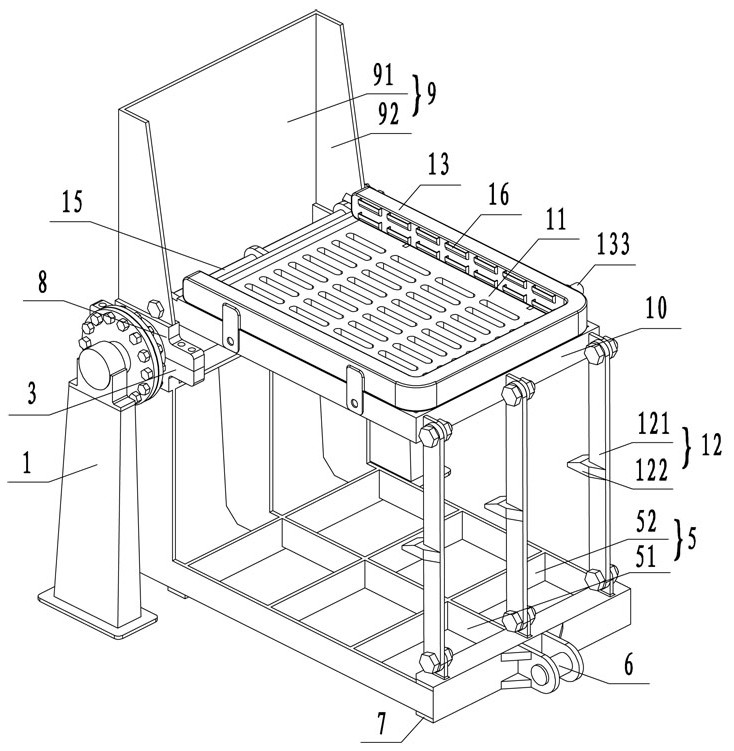
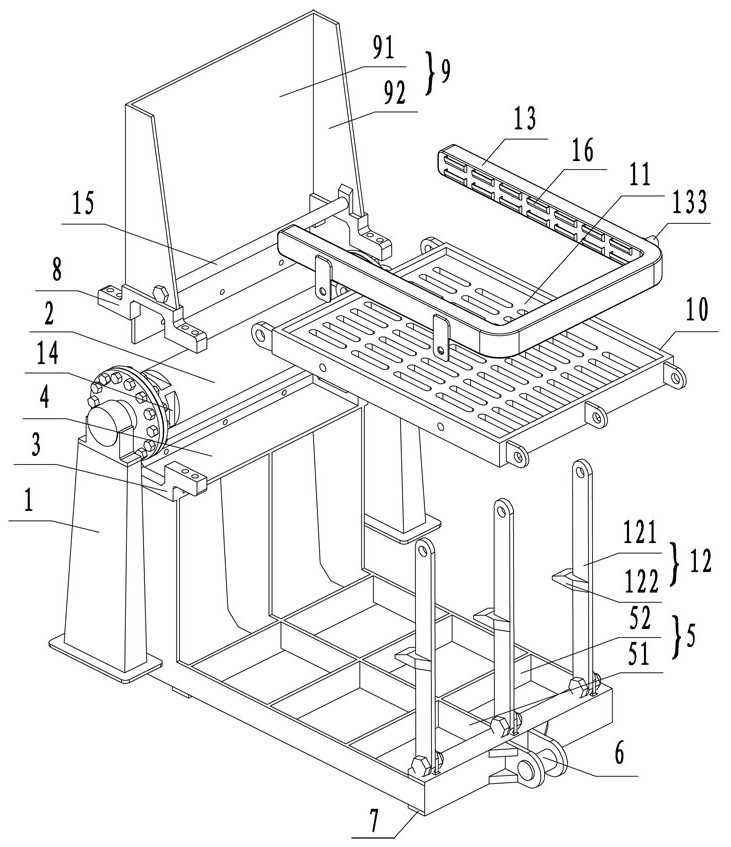
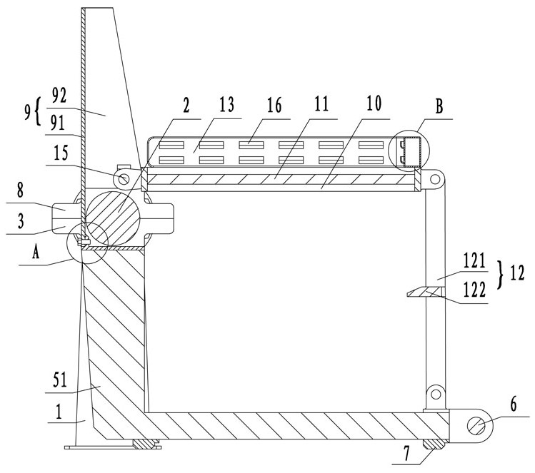
[0032] like Figure 1~Figure 6 As shown, a casting sand box turning machine includes a rotary unit, a bearing unit for carrying the sand box, a chute unit for sand falling, and a limiting unit for limiting the sand box. The rotary unit includes two sides The bracket 1 and the rotary shaft 2 that is rotatably arranged between the brackets 1 on both sides, the rotary shaft 2 is located at the top of the bracket 1, and the two ends of the rotary shaft 2 are symmetrically provided with slots 14.

[0033] Taking the radial direction of the rotary shaft 2 as the center of symmetry, the lower part of the rotary shaft 2 is provided with the bearing unit. The bearing unit includes the lower decks 3 on both sides, the connecting plates 4 fixedly connected to the decks on both sides, and the connecting plates fixedly arranged on the connecting plates. The "L" shaped bracket 5 below the plate 4, the bracket 5 is used to carry the sand box;

[0034] Specifically, the bracket 5 includes th...

Embodiment 2

[0050] like Figure 7 As shown, this embodiment is basically the same as Embodiment 1, and the similarities will not be repeated. The difference is that in this embodiment, no driving is set as the turning power, and the bracket 1 on one side is provided with a geared motor 17, so The deceleration motor 17 is connected to the rotary shaft 2 through transmission, and the deceleration motor 17 is used as the turning power to perform the operation of turning over the box and dumping sand.


PUM


Abstract

The invention relates to a casting sand box turnover machine. The casting sand box turnover machine comprises a rotary unit, a bearing unit, a chute unit and a limiting unit, wherein the rotary unit comprises brackets on both sides and a rotary shaft which is rotatably arranged between the brackets on the both sides; the bearing unit is arranged on the lower part of the rotary unit, and the bearing unit comprises lower clamping seats on both sides, a connecting plate which is used for connecting the clamping seat on the both sides and a support frame which is arranged below the connecting plate; the chute unit is arranged on the upper part of the rotary shaft, the chute unit comprises upper clamping seats on both sides and a chute which is connected with the upper clamping seats on the both sides, and the upper clamping seats and the lower clamping seats are buckled on the rotary shaft; and the limiting unit is rotatably arranged in the chute, the limiting unit comprises a limiting frame and a grate plate which is arranged in the limiting frame, a plurality of connecting rods are arranged between the limiting frame and the support frame, and a dust hood is arranged on the upper part of the limiting frame. The casting sand box turnover machine has the advantage of the reasonable structure, casting sand and castings can be preferably separated once, the diffusion of flying dust can be avoided, and the clean operating environment is guaranteed.

Description

technical field [0001] The invention relates to the technical field of V-method casting, in particular to a casting sand box turning machine. Background technique [0002] V-method casting uses plastic film to seal the sand box, and the air in the mold is drawn out by the vacuum pumping system. There is a pressure difference between the inside and outside of the mold, which makes the dry sand dense and forms the required cavity. The casting is solidified, the negative pressure is released, and the molding sand collapses to obtain the casting. [0003] After the required castings are obtained, the sand box needs to be placed on the box turning machine. The worker is in the sand shakeout position and operates the box turner to turn the box and dump the sand to take out the model and castings. As far as the sand shakeout position is concerned, the safety factor is low. When pouring the sand, the flying dust is so diffuse that the working environment is poor and the pollution i...

Claims


Application Information

Patent Timeline
IPC IPC(8): B22D29/04B22D45/00B08B15/04
CPCB08B15/04B22D29/04B22D45/005
Inventor 张鹏保五生张天兴张旭
Owner ZHENGZHOU YUSHENG CASTING CO LTD
Why Eureka
Try Eureka