Naked eye 3D local holographic display method

A holographic display and 3D technology, applied in the field of 3D display, can solve the problems of immaturity, different images, motion parallax, etc.

Active Publication Date: 2020-11-17
陈蜀乔
View PDF9 Cites 0 Cited by
  • Summary
  • Abstract
  • Description
  • Claims
  • Application Information

AI Technical Summary

Problems solved by technology

[0003] 1. Binocular parallax is different from the distance between two human eyes (the average value is 6.5cm), so for the same scene, the relative positions of the left and right eyes are different, which results in binocular parallax, that is, what the left and right eyes see is different. difference image;
[0004] 2. Motion Parallax
However, there is no mature technology to realize naked-eye 3D display, especially local holographic display.

Method used


Image

  • Naked eye 3D local holographic display method
  • Naked eye 3D local holographic display method
  • Naked eye 3D local holographic display method

Examples


Embodiment approach 1

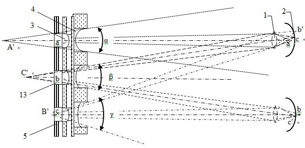
[0056] Embodiment 1: The focal length of the scene in front is measured in partitions to obtain the depth of field information. Part: In order to realize the modulation of the light emitting angle of the light source, a modulation voltage signal needs to be applied U α Focus the lens (4) on the conductive liquid, and to obtain the modulated voltage signal, the focal length signal must be obtained, because the focal length signal A represents the distance between the diffuse reflection point of the real object and the camera, and the focal length signal can be converted into a modulated voltage Signal U α , it is unrealistic to measure the focal length of each real object diffuse reflection light spot, so the method of partition measurement is used for measurement, and the part of obtaining the depth of field information includes:

[0057] - light-shielding wall (14) for blocking side light;

[0058] -Vertical light channel (15), used to filter the incoming light and obtain ...

Embodiment approach 2

[0081] Embodiment 2: a naked-eye 3D local holographic display method, characterized in that it includes a part for obtaining depth of field information by partition measurement of the focal length of the front scene and a naked-eye 3D local holographic display including part;

[0082] Part of the divisional measurement of the focal length of the front scene to obtain the depth of field information: in order to realize the modulation of the light emitting angle of the light source, a modulation voltage signal needs to be applied U α Focus the lens (4) on the conductive liquid, and to obtain the modulated voltage signal, the focal length signal must be obtained, because the focal length signal A represents the distance between the diffuse reflection point of the real object and the camera, and the focal length signal can be converted into a modulated voltage Signal U α , it is unrealistic to measure the focal length of each real object diffuse reflection light spot, so the met...


PUM


Abstract

The technical problem to be solved by the invention is to provide a naked eye 3D local holographic display method, and belongs to the technical field of three-dimensional display. The method comprisesa front scenery focal length partition measurement depth-of-field information acquisition part and a naked eye 3D local holographic display part. Naked eye 3D local holographic display comprises primary focusing, accurate adjustment of the light-emitting angle of light-emitting pixels, a 3D display driving circuit, pixel circuit driving and three-dimensional pixel taper angle axis pointing. A tiny liquid focusing lens is additionally arranged on each pixel of an existing display screen, diffuse reflection of common pixels is changed into control over the light-emitting angle of each pixel ora plurality of pixel light sources, naked-eye 3D local holographic display is achieved, the image display principle is consistent with the fundus projection effect of a real scene image seen by nakedeyes. Brain imaging does not cause extra burden, headache and eye fatigue are avoided after eyes are used for a long time, and the display screen has rigid market requirements.

Description

technical field [0001] The invention relates to a naked-eye 3D local holographic display method, which belongs to the technical field of 3D display. Background technique [0002] At present, naked-eye 3D display has always been the technical bottleneck that flat-panel displays are trying to break through. The reasons why human naked eyes can see 3D images are as follows: [0003] 1. Binocular parallax is different from the distance between two human eyes (the average value is 6.5cm), so for the same scene, the relative positions of the left and right eyes are different, which results in binocular parallax, that is, what the left and right eyes see is different. difference image; [0004] 2. Motion parallax. Motion parallax is produced by the relative movement between the observer and the scene, which changes the size and position of the scene on the projection of the retina, resulting in a sense of depth; [0005] 3. The adjustment function of the eyes (adaptive adjustme...

Claims


Application Information

Patent Timeline
Patent Type & Authority Applications(China)
IPC IPC(8): G03B35/00H04N13/302G03H1/22G09G3/3208G03B13/36G02B26/00G02B3/14
CPCG03B35/00H04N13/302G03H1/2205G09G3/3208G03B13/36G02B26/005G02B3/14
Inventor 陈蜀乔
Owner 陈蜀乔
Why Eureka
Try Eureka