Stainless steel surface stud welding device

A stud welding and stainless steel technology, applied in auxiliary devices, welding equipment, welding equipment, etc., can solve the problems of high error rate, long time for sample production, low efficiency, etc., and achieve the effect of improving welding efficiency

Pending Publication Date: 2020-12-04
JIANGSU TONGLI MACHINERY
View PDF0 Cites 1 Cited by
  • Summary
  • Abstract
  • Description
  • Claims
  • Application Information

AI Technical Summary

Problems solved by technology

[0004] Aiming at the deficiencies of the prior art, the present invention provides a stainless steel surface stud welding device, which can conveniently and quickly perform stud welding on stainless steel plates, and at the same time can be positioned for different stainless steel plates, which is conducive to quickly improving the stud welding of stainless steel plates. The advantage of efficiency solves the problems that when the existing device is in use, the manual welding machine needs to be nailed manually, the error rate is high, the sample making time is long, and the efficiency is low

Method used


Image

  • Stainless steel surface stud welding device
  • Stainless steel surface stud welding device
  • Stainless steel surface stud welding device

Examples


Embodiment 1

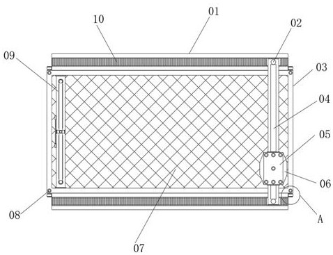
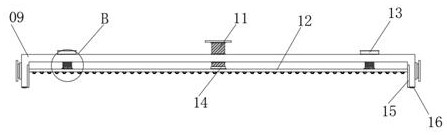
[0031] see figure 1 : Including the working board 03, the top of the working board 03 is provided with a square groove, and the hollow board 07 is fixedly connected, the top and the bottom of the working board 03 are fixedly connected with the baffle 01, and the baffle 01 is an "L" shaped structure, The inner side of the horizontal wall of the baffle plate 01 is provided with a bar-shaped groove and a slide rail 10 is installed. The inner side of the slide rail 10 is provided with a positioning stud 02. The bottom of the positioning stud 02 is square and is slidably connected with the inside of the slide rail 10. The outer side of the cylinder of the positioning stud 02 is sleeved with a sliding rod 04, the outer side of the sliding rod 04 is slidably connected with a welding device 05, the outer side of the welding device 05 is provided with a control board 06, and the top of the welding device 05 is provided with a circular through hole And it is fixedly connected with a del...

Embodiment 2

[0033] see Figure 4 : the outside of the limiting ring 26 is equidistantly provided with several bar-shaped grooves, and bolts 27 are installed at the bar-shaped grooves, and threaded through holes are equidistantly provided at the four peripheral corners of the top of the connecting frame 25, and the threaded through holes A bolt 30 is threadedly connected at the place, and the bottom of the working plate 03 penetrates through the bolt 30 .

Embodiment 3

[0035] see Figure 5 : the left and right sides of the baffle plate 01 are fixedly connected with an extension block 32, and the block body of the extension block 32 is provided with a threaded through hole, and the threaded through hole is threaded with a threaded post 31, and one end of the threaded post 31 is connected to the working The outside of the plate 03 is screwed together.


PUM


Abstract

The invention relates to the technical field of stainless steel plate welding, and particularly discloses a stainless steel surface stud welding device. The device comprises a working plate, a squaregroove is formed in the top of the working plate, a hollowed-out plate is fixedly connected to the top of the working plate, baffles are fixedly connected to the top and the bottom of the working plate, each baffle is of an L-shaped structure, strip-shaped grooves are formed in the inner sides of the horizontal walls of the baffles, and sliding rails are installed on the inner side of the horizontal walls of the baffles. According to the stainless steel surface stud welding device, arranged positioning studs can be matched with arranged sliding rods so that the welding device can stably move above the working plate; meanwhile, the position of the welding device can be conveniently changed according to the position requirements of different steel plate welding bolts under the action of thesliding rails; the welding positions of the studs can be controlled according to the actual situation in the using process through the cooperation of a control panel; and stainless steel plates can beclamped according to the welding requirements of different stainless steel plates in the using process through an arranged clamp in cooperation with the arranged hollowed-out plate.

Description

technical field [0001] The invention relates to the technical field of stainless steel plate welding, in particular to a stainless steel surface stud welding device. Background technique [0002] Escalators can be seen everywhere in large and small shopping malls, airports, subway stations, etc. Escalators are indispensable everywhere. The market is huge. With the development of rural urbanization in the country, the demand for escalators will only increase. Moreover, the escalator not only has a huge domestic market, but also has a huge foreign market. With the increase in demand for the same order, every elevator needs stud welding, so the research and application of automatic welding and fast welding is the trend of market development, and it is also a must for factory production. In response to the requirements of reducing production costs, increasing sales, and high production efficiency, the original manual stud welding process urgently needs to be improved and improv...

Claims


Application Information

Patent Timeline
Patent Type & Authority Applications(China)
IPC IPC(8): B23K9/20B23K9/32B23K37/04
CPCB23K9/20B23K9/32B23K37/0443
Inventor 李国平
Owner JIANGSU TONGLI MACHINERY
Why Eureka
Try Eureka