Cave plug flood discharging cave connected through open channel

A technology for flood discharge tunnels and plugs, which is applied in the field of flood discharge tunnels, can solve the problems of high pressure, increased risk of engineering damage, and unfavorable cavitation and cavitation in the plug section of flood discharge tunnels, so as to reduce hydrodynamic loads and achieve good consumption. energy effect, the effect of reducing dynamic load

Inactive Publication Date: 2020-12-08
SICHUAN UNIV
View PDF7 Cites 0 Cited by
  • Summary
  • Abstract
  • Description
  • Claims
  • Application Information

AI Technical Summary

Problems solved by technology

[0003] Existing plug flood discharge tunnels generally have the following disadvantages: 1. In the case of large flow and high head water flow, the reservoir and the flood discharge tunnel are connected by pressurized pipes, and the water flow in the pipe is pressurized flow
Often in actual engineering, the pressure at the bottom plate of the shaft section is the highest, and it will increase with the rise of the reservoir water level. The water flow directly impacts the bottom plate, and deformation occurs under the action of hydrodynamic load, which increases the risk of engineering damage
2. Under normal circumstances, the working gate is set at the entrance position, which will cause the problem of no water in the shaft section at the beginning of the gate opening, and the air in the tunnel will be carried to the plug section at the beginning of the gate opening, and there will be a clear and full flow transition in the flood discharge tunnel The flow state is not conducive to the prevention of cavitation and cavitation in the plug section of the flood discharge tunnel

Method used


Image

  • Cave plug flood discharging cave connected through open channel
  • Cave plug flood discharging cave connected through open channel
  • Cave plug flood discharging cave connected through open channel

Examples


Embodiment 1

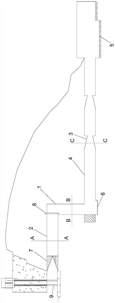
[0023] Example 1: See Figure 1 to Figure 5 , a plug flood discharge tunnel connected by an open channel in this embodiment includes an inlet section 7, an open channel section 2, a shaft section 1, a lower flat section 4, and a plug section 3 arranged sequentially along the water flow direction; the open channel section 2 and the vertical shaft Section 1 is vertically connected, vertical shaft section 1 is vertically connected with lower flat section 4, and the top of open channel section 2 is connected with the outside atmosphere, and then the water flow changes from unpressurized flow to pressurized flow; the number of hole plug sections 3 is multiple, and they are closely connected to each other . The connection mode, structure and layout of the hole plug energy dissipator are improved, which can reduce the dynamic load of the bottom plate of shaft section 1 and facilitate the discharge of air in the shaft. During flood discharge, the water flow in the reservoir flows int...

Embodiment 2

[0024] Embodiment 2: The cross section of the open channel section 2 in this embodiment is a rectangle with an open top. After the unpressurized water flow in the open channel enters the shaft, the gas in the water can be smoothly discharged from the top of the shaft, which can eliminate the gas explosion phenomenon at the end of the spillway tunnel and is conducive to protecting the safety of the tunnel lining structure. It can effectively reduce the hydrodynamic load acting on the bottom plate of shaft section 1. The plug section 3 of this embodiment includes a plug portion, and the inner diameter of the plug portion decreases gradually along the water flow direction. The sudden contraction of the water flow can reduce the energy of the high-speed water flow. The cross section of the plug segment 3 in this embodiment is circular. The number of the plug segments 3 in this embodiment is two, and the two plug segments 3 are connected, and the water inlet end of the first plug...

Embodiment 3

[0025] Embodiment 3: An outlet stilling basin 5 is provided after the plug section 3 in this embodiment, and the height of the outlet stilling basin 5 is lower than that of the plug section 3 . Energy dissipation facilities are added outside the tunnel, which can not only dissipate the residual energy at the end of the flood discharge tunnel, but also use the 5 tail sills of the exit stilling pool to retain water, so that it is convenient to enter the tunnel for inspection when the water level in the downstream is low. The stilling pool 5 at the exit of the cave is set to eliminate the kinetic energy of the high-speed water flow at the exit of the cave body, which can greatly reduce the water flow velocity at the exit of the cave body, so as to reduce the erosion of the exit of the cave body and downstream river courses and bank slopes. The multi-stage shrinkable hole plug 3 inside the cave and the stilling pool 5 outside the cave form a combined energy dissipator to jointly re...


PUM


Abstract

The invention discloses a cave plug flood discharging cave connected through an open channel. The flood discharging cave comprises an inlet section, an open channel section, a vertical shaft section,a lower flat section, and cave plug sections which are sequentially arranged in the water flow direction. The open channel section is vertically communicated with the vertical shaft section; the vertical shaft section is vertically communicated with the lower flat section; the number of the cave plug sections is multiple; and the cave plug sections are closely connected with one another. The connecting mode, the structure and the arrangement mode of a cave plug energy dissipater are improved, the dynamic load of a bottom plate of the vertical shaft section can be reduced, and air in a verticalshaft can be exhausted easily. During flood discharging, water flow in a reservoir flows into the vertical shaft from the open channel and is changed into pressure flow from non-pressure flow, so that the reduction of the hydrodynamic load acting on the bottom plate of the vertical shaft section and the discharge of the air in a cave are facilitated. The flood discharging cave plug section adoptsmulti-stage contraction type plugs, which is good in energy dissipation effect, and can adapt to high-flow and high-water-head working conditions.

Description

technical field [0001] The invention relates to the technical field of energy dissipation in water conservancy and hydropower projects, in particular to a plug flood discharge tunnel connected by an open channel. Background technique [0002] The principle of hole plug energy dissipation is to reduce the energy of high-speed water flow by reducing the hole diameter of the section where the hole plug is located, and to reduce the energy of high-speed water flow by using the sudden contraction and expansion of the water flow through the hole plug to reduce the flow velocity of the downstream water flow and reduce the Downstream river bed scour. In the actual project, the flood discharge tunnel has the characteristics of low position, submerged outlet, and strong pressure inside the tunnel. The energy dissipation of the plug can make full use of these characteristics, greatly improving its energy dissipation effect, and reducing the risk of cavitation damage at the same time. ...

Claims


Application Information

Patent Timeline
Patent Type & Authority Applications(China)
IPC IPC(8): E02B8/06
CPCE02B8/06
Inventor 田忠朱艳德王韦许唯临刘善均张建民邓军曲景学张法星
Owner SICHUAN UNIV
Why Eureka
Try Eureka