A fixed anti-slip locking device and a multi-function bar containing the device
A multi-functional, locking technology, which is applied to the components of lighting devices, lighting devices, lighting auxiliary devices, etc., can solve the problems of affecting the fixing effect and strength, poor fastening effect, loose bolts, etc., and achieve simplified installation Easy to operate, easy to adjust, easy to disassemble and replace
- Summary
- Abstract
- Description
- Claims
- Application Information
AI Technical Summary
Problems solved by technology
Method used
Image

Examples
Embodiment 1
[0059] Embodiment 1: A fixed anti-slip locking device that is easy to install and expand. The groove matches the metal clip 3A, and a spring 4A and a mounting screw 5A are sequentially arranged between the metal clip 3A and the equipment mounting part 2A. The metal clip 3A includes a clip body 301, two ends of the clip body 301 are provided with a block 302, the block 302 is provided with a mounting screw hole 304, and one end of the mounting screw hole 304 is provided with a spring mounting hole 305. A groove 306 is formed at the other end of the mounting screw hole 304 . The clamping block 302 is provided with toothed anti-skid lines 303 ; the middle of the clamping body 301 is also provided with a vertically penetrating mounting screw hole 304 , and one end of the mounting screw hole 304 is provided with a spring mounting hole 305 . A groove 306 is formed at the other end of the mounting screw hole 304 . The outer end surface of the clamping block 302 is an arc surface 30...
Embodiment 2
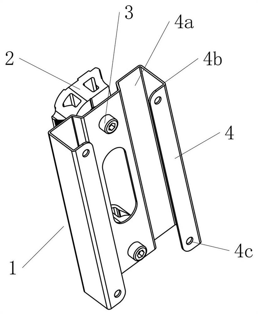
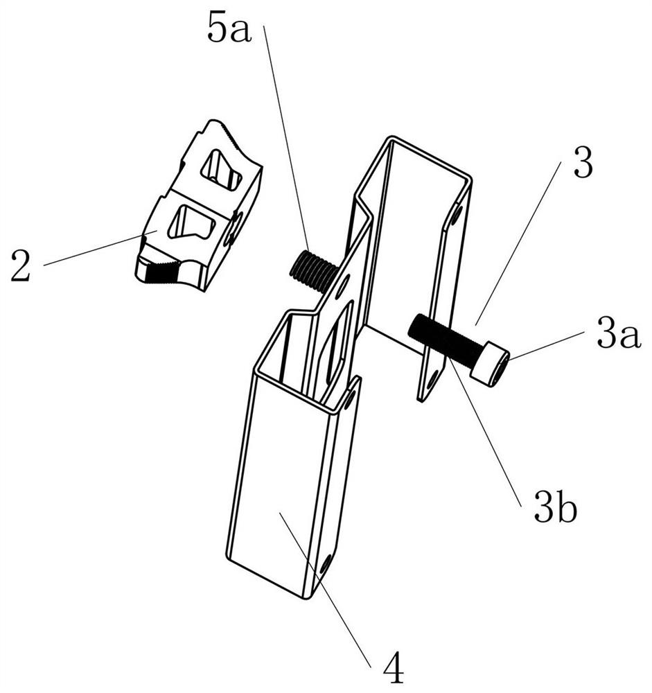
[0062] Embodiment 2: A connection device 1 that is easy to install, including an equipment mounting base 4, an abutment base 4a connected to the equipment installation base 4, a block 2 and a locking member for the abutment base 4a 3. The abutment base 4a and the equipment mounting seat 4 are fixedly connected to each other, and a through hole 4aa for passing the locking member 3 is opened on the abutting base 4a; the locking member 3 is cylindrical and includes radial The lock head 3a whose size is larger than the through hole 4aa and the screw rod 3b whose radial size is smaller than the through hole 4aa and which is provided with threads on the outer side; the block 2 is provided with threads for connecting with the screw rod 3b The connecting portion 2a is specifically a threaded hole opened at the center of the front end of the block 2 and extending to the opposite side. The locking member 3 passes through the through hole 4aa on the abutting base 4a and is connected to ...
Embodiment 3
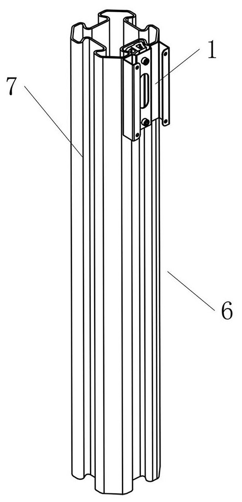
[0064] Embodiment 3: A multifunctional rod 6 comprising the easy-to-install connection device 1 described in Embodiment 1, the multi-function rod 6 includes a special-shaped rod for fixed connection with the easy-to-install connection device 1 7. The special-shaped rod 7 includes several supporting walls 8a, mounting walls 8b and connecting walls 8c, the supporting walls 8a, mounting walls 8b and connecting walls 8c are interconnected to form mounting grooves 8, and the mounting grooves 8 are located in The side of the special-shaped rod 7 extends along the axial direction of the special-shaped rod 7. The installation groove 8 includes an opening 8d on the outside and a receiving part 8e on the inside. The width of the opening 8d is smaller than that of the receiving part. 8e, at this time, in the installation groove 8, an engaging portion 8f that is connected to the support wall 8a and the installation wall 8b protrudes from both sides to the middle and is used for mating conn...
PUM
 Abstract
Description
Claims
Application Information
 - R&D
- Intellectual Property
- Life Sciences
- Materials
- Tech Scout
- Unparalleled Data Quality
- Higher Quality Content
- 60% Fewer Hallucinations
Browse by: Latest US Patents, China's latest patents, Technical Efficacy Thesaurus, Application Domain, Technology Topic, Popular Technical Reports.
© 2025 PatSnap. All rights reserved.Legal|Privacy policy|Modern Slavery Act Transparency Statement|Sitemap|About US| Contact US: help@patsnap.com