Automatic take-up and pay-off mechanism for mooring rotor wing and using method thereof

A technology of automatically retracting and releasing the wire and mooring the rotor, which is applied in the field of drones, can solve problems such as easy knotting, increased workload, and potential safety hazards, and achieve the effects of improving practicability, facilitating wire retraction, and facilitating retraction

Active Publication Date: 2021-02-09
湖南浩天翼航空技术有限公司
View PDF9 Cites 1 Cited by
  • Summary
  • Abstract
  • Description
  • Claims
  • Application Information

AI Technical Summary

Problems solved by technology

[0004] The purpose of the present invention is to solve the disadvantages in the prior art that the automatic winding cannot be realized, resulting in a single function, low practicability, and not timely winding, prone to knotting, increased workload, and easy to cause safety hazards. A Tethered Rotor Automatic Retracting and Unwinding Mechanism Proposed and Its Application Method

Method used


Image

  • Automatic take-up and pay-off mechanism for mooring rotor wing and using method thereof
  • Automatic take-up and pay-off mechanism for mooring rotor wing and using method thereof
  • Automatic take-up and pay-off mechanism for mooring rotor wing and using method thereof

Examples


Embodiment 1

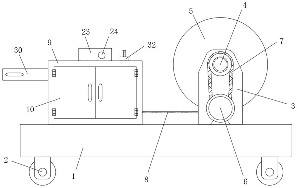
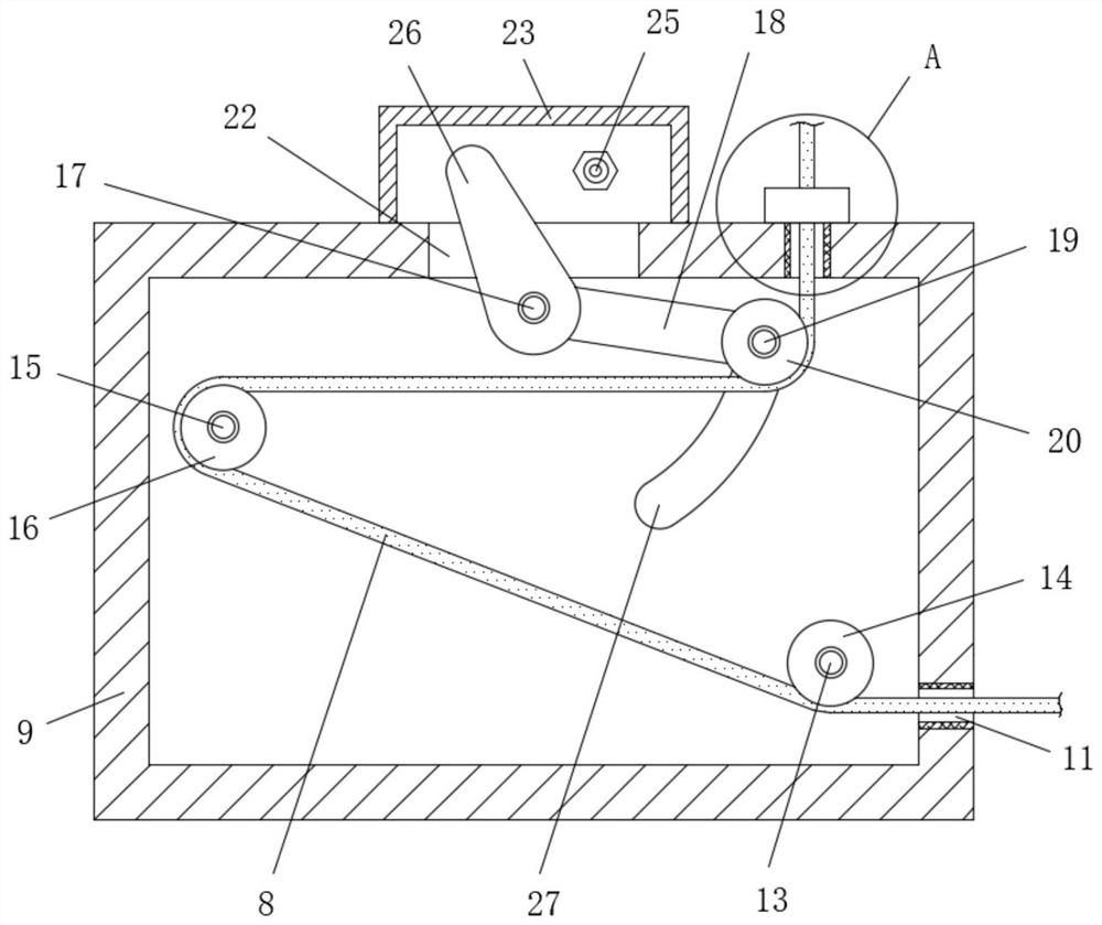
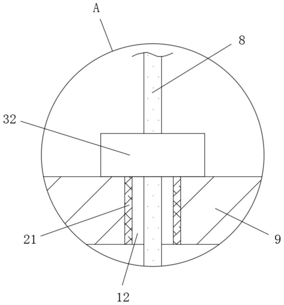
[0031] refer to Figure 1-7 , a tethered rotor automatic take-up and release mechanism, including a base 1, the four corners of the bottom of the base 1 are provided with universal wheels 2, the top side of the base 1 is fixedly connected with a mounting frame 3, and the mounting frame 3 is rotated and connected There is a roller shaft 4, the winding roller 5 is fixedly set on the roller shaft 4, the motor 6 is fixedly connected to the top of the base 1, one side of the roller shaft 4 extends to the outside of the mounting frame 3 and is connected with the output shaft of the motor 6 There is the same belt 7, and the winding roller 5 is wound with a cable 8, and the other side of the top of the base 1 is fixedly connected with a wiring box 9, and one side of the wiring box 9 is provided with a box door 10, and the wiring box 9 A wire inlet 11 is opened at the bottom of one side close to the installation frame 3, and a wire outlet 12 is opened at the top of the wire box 9 near ...


PUM


Abstract

The invention discloses an automatic take-up and pay-off mechanism for a mooring rotor wing and a using method thereof. The automatic take-up and pay-off mechanism comprises a base, wherein universalwheels are arranged at four corners of the bottom of the base; one side of the top of the base is fixedly connected with a mounting frame; a roller shaft is rotatably connected on the mounting frame;a winding roller is fixedly arranged on the roller shaft in a sleeving mode; the top of the base is fixedly connected with a motor; one side of the roller shaft extends to the outer side of the mounting frame, and is in transmission connection with the same belt with an output shaft of the motor; and a cable is wound on the winding roller. According to the automatic take-up and pay-off mechanism disclosed by the invention, a cable inlet guide wheel, a cable passing guide wheel and a cable outlet guide wheel are matched, so that the cable is conveniently taken up and paid off; meanwhile, a balancing weight is matched with the cable outlet guide wheel, so that a convex plate can be driven to swing, and therefore, the automatic take-up effect is realized through matching with a light source emitter and a photoelectric sensor; and moreover, balancing weights with different weights can be suitable for different pulling forces, on the cable, of wind power of different environments, so that practicability is improved.

Description

technical field [0001] The invention relates to the technical field of unmanned aerial vehicles, in particular to a tethered rotor automatic retracting and releasing mechanism and a method for using the same. Background technique [0002] The tethered UAV is a UAV system that combines the UAV and the tethered integrated cable. The tethered UAV transmits electrical energy through the photoelectric integrated cable, so that the UAV can stay in the area for a long time without being limited by the electrical energy. In the air, its structure size and production materials can be flexibly designed according to the application requirements, and the maneuverability is strong. According to different application scenarios, the tethered UAV system is divided into three types: ground fixed, vehicle-mounted mobile and ship-borne mobile. The working style satisfies the needs of various working environments very well. [0003] However, the currently existing tethered UAV take-up and rele...

Claims


Application Information

Patent Timeline
Patent Type & Authority Applications(China)
IPC IPC(8): B65H75/38
CPCB65H75/38B65H2701/34
Inventor 刘明星熊哲李昌
Owner 湖南浩天翼航空技术有限公司
Why Eureka
Try Eureka