
Weak current network power distribution cabinet
An electrical network and power distribution cabinet technology, applied in the substation/distribution device casing, electrical components, substation/switch layout details, etc., can solve the problems of inconvenient storage, disorderly storage of wires, inconvenient access, etc. The effect of clear leads and increased length
- Summary
- Abstract
- Description
- Claims
- Application Information
AI Technical Summary
Problems solved by technology
Method used
Image

Examples
Embodiment approach
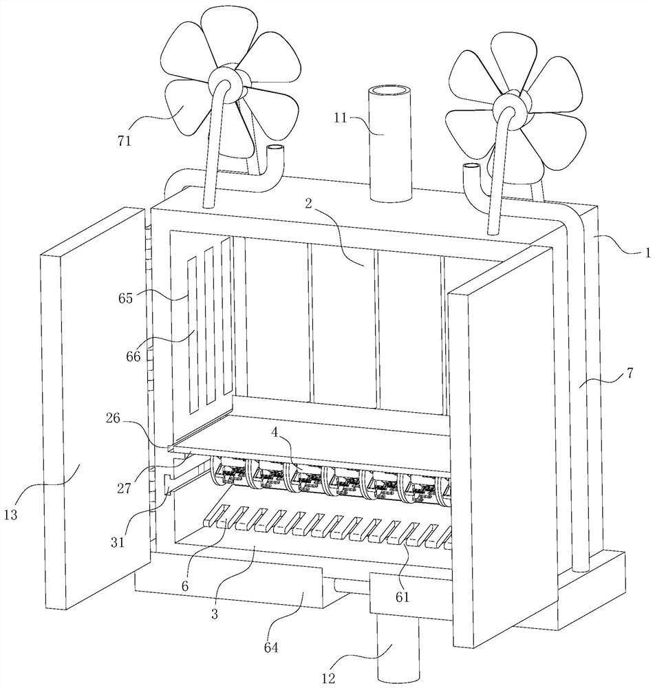
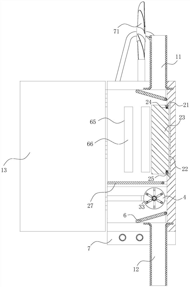
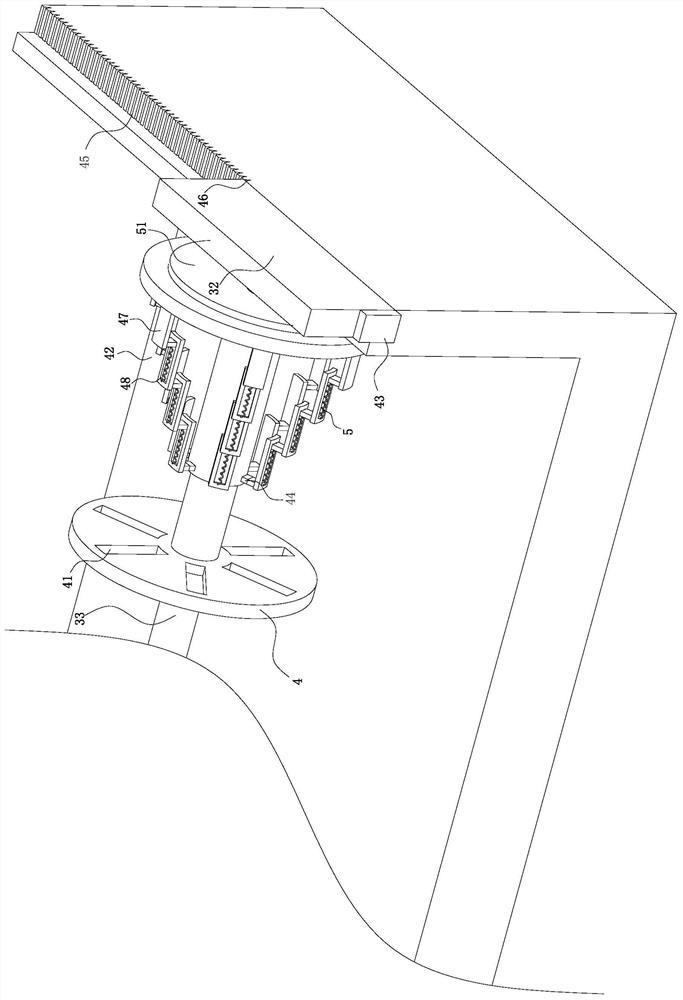
[0030] As an embodiment of the present invention, the side of the sliding plate 32 away from the cabinet door 13 is fixedly connected with an air suction bag 43; The bag 44; the expansion bag 44 and the suction bag 43 are designed to be conducted through the catheter; the side of the extension plate 42 away from the support rod 33 is designed with a smooth arc surface; during work, when the wire is wound, the sliding plate 32 is first and the support rod 33 are pulled outwards along the second chute 31, and the air-pumping bag 43 is stretched when the sliding plate 32 moves, and then the air-pumping bag 43 is deformed to extract the gas in the expansion bag 44, and then the expansion bag 44 is contracted, so that the extension plate 42 All move towards the support rod 33. After winding the wires, move the sliding plate 32 and the support rod 33 to the inside of the second chute 31 again. The volume increases, and the extension plate 42 is pushed to slide in the third chute 41,...
PUM
 Abstract
Description
Claims
Application Information