Push rod type three-locking two-unlocking lock and equipment with lock

A push rod type lock technology, applied in the field of locks, can solve problems such as inability to unlock, heavy weight, and insufficient unlocking force, and achieve the effect of convenient unlocking

Active Publication Date: 2021-02-23
SGSG SCI & TECH CO LTD
View PDF3 Cites 0 Cited by
  • Summary
  • Abstract
  • Description
  • Claims
  • Application Information

AI Technical Summary

Problems solved by technology

In order to increase the safety factor of locks, in the current financial security products, three locks and two openings are used on the vault door and safe door. The bolt of the lock is usually mechanically driven to unlock, which cannot be applied
Existing relatively large locks such as vault doors and storage cabinet doors, due to their own weight, if they are unlocked solely by electric drive, the unlocking force is not enough, so that the unlocking cannot be completed.

Method used


Image

  • Push rod type three-locking two-unlocking lock and equipment with lock
  • Push rod type three-locking two-unlocking lock and equipment with lock
  • Push rod type three-locking two-unlocking lock and equipment with lock

Examples


Embodiment 1

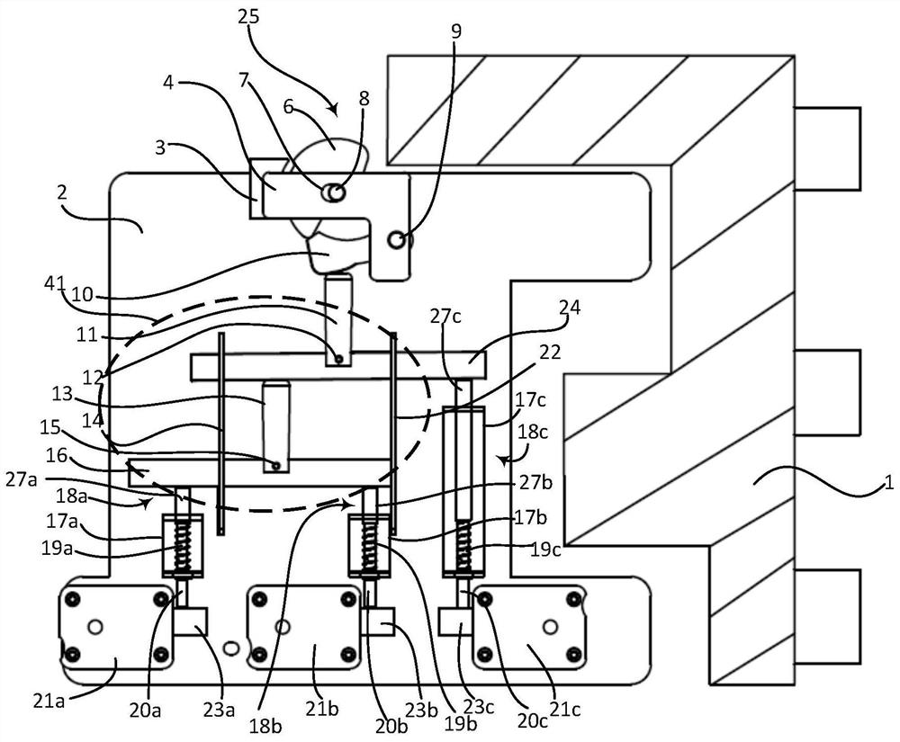
[0053] See attached figure 1 ~ attached Figure 6 The push-rod type three-lock-two-unlock device provided in Embodiment 1 of the present invention includes a driving assembly 25 , a base 2 , three locks 21 , a cantilever transmission assembly 41 and three push rods 18 . Three locks 21 are fixed on the base 2 . The cantilever transmission assembly 41 has three free ends, the first ends of the three push rod assemblies 18 touch the three free ends one by one, and the second ends of the three push rod assemblies 18 are arranged on the three free ends one by one. The deadbolt positions of the three locks 21 are such that when any two of the three locks 21 are in the unlocked position and the cantilever transmission assembly 41 is driven by the drive assembly 25 to move in a set direction, the corresponding two push rod assemblies 18 can move along the set direction. Set direction to move.

[0054] In this embodiment, the cantilever transmission assembly 41 includes a first cant...

Embodiment 2

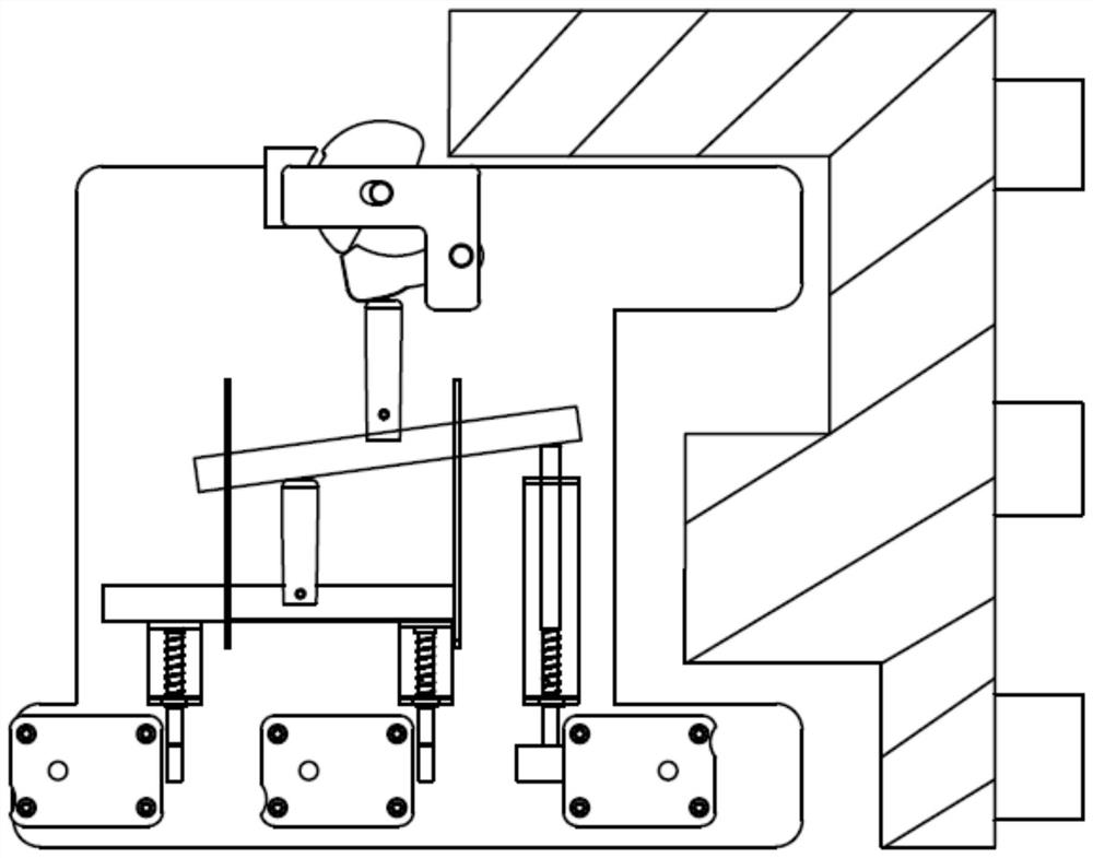
[0069] See attached Figure 7 And attached Figure 8 The difference from the push rod type three-lock and two-unlocking device provided in Embodiment 1 of the present invention is that in the push rod type three-lock and two-unlocking device provided in Embodiment 2 of the present invention, the push rod assembly 18 includes a lever body 38 , pry rocker 39. The first end of the prying rod body 38 touches the free end of the cantilever transmission assembly, the second end of the prying rod body 38 is fixedly connected to the first end of the prying seesaw 39, and the second end of the prying seesaw 39 One-to-one correspondence is provided at the bolt positions of the three locks 21; the prying seesaw 39 is hinged to the base 2 through its middle. In this embodiment, the prying rod body 38 includes a first prying rod body 38a, a second prying rod body 38b, and a third prying rod body 38c. The prying seesaw 39 includes a first prying seesaw 39a, a second prying seesaw 39b and...

Embodiment 3

[0072] The device with a lock provided in Embodiment 3 of the present invention includes the push-rod type three-lock-two-unlocking device provided in Embodiment 1 or Embodiment 2 of the present invention.

[0073] When using the device with a lock provided in Embodiment 3 of the present invention, push the driving assembly 25 to the left, and the first cantilever 11 will act on the first seesaw 24 after being pushed by the drive assembly 25. Since the first end of the first seesaw 24 Touching the second cantilever 13, the second cantilever 13 further drives the movement of the second seesaw 16, wherein, the second end of the first seesaw 24, the first end of the second seesaw 16, the second seesaw The second ends of 16 respectively touch the first ends of the three push rod assemblies 18 in one-to-one correspondence. Therefore, in this case, when two of the three locks are in the unlocked position, they can be locked by applying force. The thrust exerted by the block 1 on the...


PUM


Abstract

The invention discloses a push rod type three-locking two-unlocking lock and equipment with the lock, and belongs to the technical field of locks. The lock comprises a driving assembly (25), a base (2), three locks (21), a cantilever type transmission assembly (41) and three push rod assemblies (18). The three locks (21) are fixedly arranged on the base (2), the cantilever type transmission assembly (41) is provided with three free ends, the first ends of the three push rod assemblies (18) make contact with the three free ends in a one-to-one correspondence mode, the second ends of the three push rod assemblies (18) are arranged at spring bolt positions of the three locks (21) in a one-to-one correspondence mode, and when any two of the three locks (21) are located at the unlocking position and the cantilever type transmission assembly (41) is driven by the driving assembly (25) to move in the set direction, the two corresponding push rod assemblies (18) can move in the set direction.The equipment with the lock comprises the lock, and the unlocking mode is more convenient.

Description

technical field [0001] The invention relates to the technical field of locks, in particular to a push-rod type three-lock-two-unlock lock and a device with a lock. Background technique [0002] The one-lock-one-unlock lockset in the prior art usually only needs one key to open, and the safety factor is relatively low. In order to increase the safety factor of locks, in the current financial security products, three locks and two openings are used on the vault door and safe door. The deadbolt of the lockset is usually mechanically driven to unlock, which cannot be applied. The larger locksets such as existing treasury doors and safekeeping cabinet doors are relatively heavy due to their own weight. If they are unlocked solely by electric drive, the unlocking strength is not enough, so that the unlocking cannot be completed. Contents of the invention [0003] In view of this, the present invention provides a push-rod type three-lock-two-unlock device and a device with a lo...

Claims


Application Information

Patent Timeline
Patent Type & Authority Applications(China)
IPC IPC(8): E05B15/00E05B15/10E05B63/14
CPCE05B15/00E05B15/10E05B63/143Y02T10/70
Inventor 马铮周晔陈家贤罗北雄
Owner SGSG SCI & TECH CO LTD
Why Eureka
Try Eureka