Optical imaging lens and imaging equipment

An optical imaging lens and imaging surface technology, applied in the field of imaging lens, can solve problems such as inability to correctly identify and alarm, poor recognition of long-distance targets, etc., and achieve the effect of ensuring reliability, quality, low sensitivity, and convenient assembly

Active Publication Date: 2021-03-12
合肥联创光学有限公司
View PDF4 Cites 3 Cited by
  • Summary
  • Abstract
  • Description
  • Claims
  • Application Information

AI Technical Summary

Problems solved by technology

[0003] In order to obtain long-distance road information, the lens is usually required to have a clear image within a small viewing angle, which is different from the current smart driving recorder on the market. The bigger the better; however, this kind of lens can’t see far away, has poor recognition of long-distance targets, and cannot correctly identify and alarm vehicles that are slightly farther away. Most of the existing lenses on the market cannot meet the above requirements well, so , it is imperative to develop a high-performance optical imaging lens that can cooperate with ADAS

Method used


Image

  • Optical imaging lens and imaging equipment
  • Optical imaging lens and imaging equipment
  • Optical imaging lens and imaging equipment

Examples


no. 1 example

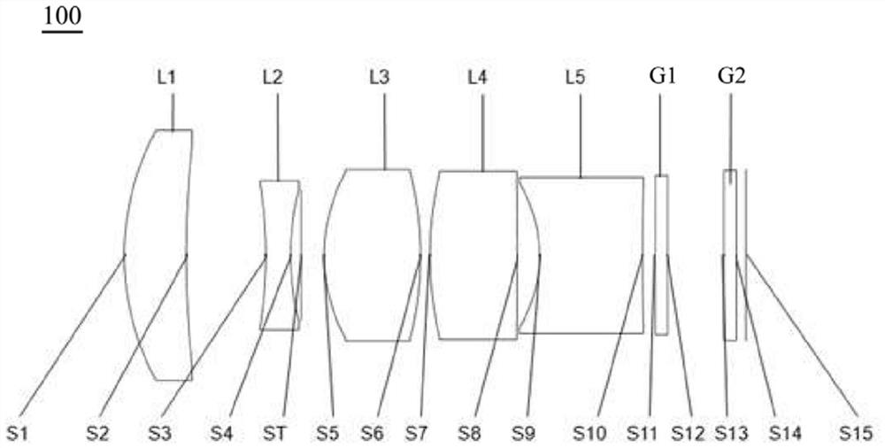
[0068] see figure 1 , which is a schematic structural view of the optical imaging lens 100 provided in the first embodiment of the present invention, the optical imaging lens 100 includes in sequence from the object side to the imaging surface along the optical axis: a first lens L1, a second lens L2, and a stop ST , the third lens L3, the fourth lens L4, the fifth lens L5, the filter G1, the protective glass G2 and the imaging surface S15.

[0069] Wherein, the first lens L1 has positive refractive power, the object side S1 of the first lens L1 is a convex surface, and the image side S2 is a concave surface;

[0070] The second lens L2 has a negative refractive power, and both the object side S3 and the image side S4 of the second lens L2 are concave;

[0071] The third lens L3 has a positive refractive power, and both the object side S5 and the image side S6 of the third lens L3 are convex;

[0072] The fourth lens L4 has a positive refractive power, and both the object si...

no. 2 example

[0083] see Figure 5 , which is a schematic structural view of the optical imaging lens 200 provided in the second embodiment of the present invention. The structure of the optical imaging lens 200 in this embodiment is roughly the same as that of the optical imaging lens 100 in the first embodiment. The radius of curvature of the lens and the choice of material are different.

[0084] The relevant parameters such as the radius of curvature, thickness, and material of each lens of the optical imaging lens 200 in the embodiment of the present invention are shown in Table 2.

[0085] Table 2

[0086]

[0087]

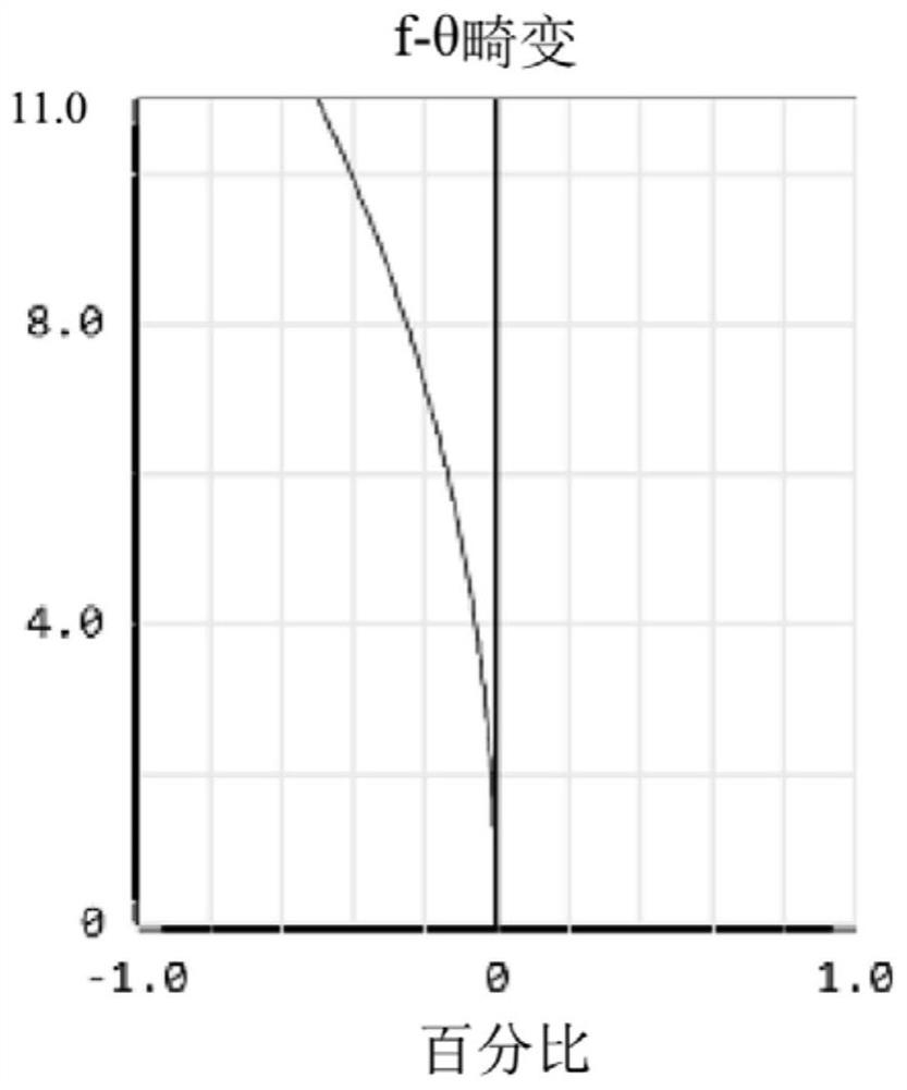
[0088] see Image 6 , shows the optical distortion curve of the optical imaging lens 200 in this embodiment, which is represented by Image 6 It can be seen that the absolute value of the optical distortion is less than 0.3% in the full field of view, indicating that the distortion has been well corrected.

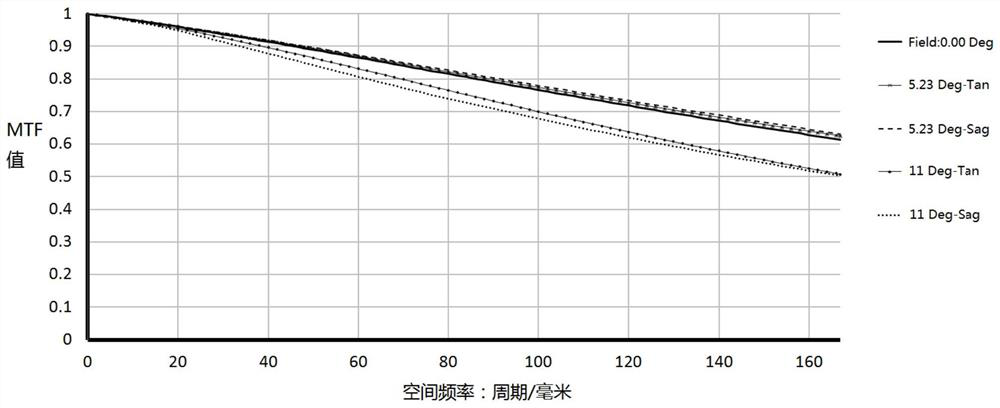
[0089] see Figure 7 with 8 , which show the MTF dia...

no. 3 example

[0091] see Figure 9 , is a schematic diagram of the structure of the optical imaging lens 300 provided in the third embodiment of the present invention. The structure of the optical imaging lens 300 in this embodiment is roughly the same as that of the optical imaging lens 100 in the first embodiment. The radius of curvature of the lens and the choice of material are different.

[0092] The relevant parameters such as the radius of curvature, thickness, and material of each lens of the optical imaging lens 300 in the embodiment of the present invention are shown in Table 3.

[0093] table 3

[0094]

[0095]

[0096] see Figure 10 , shows the optical distortion curve of the optical imaging lens 300 in this embodiment, which is represented by Figure 10 It can be seen that the absolute value of the optical distortion is less than 0.05% in the full field of view, indicating that the distortion has been well corrected.

[0097] see Figure 11 with 12 , which show th...


PUM


Abstract

The invention discloses an optical imaging lens and imaging equipment. The optical imaging lens sequentially comprises a first lens, a second lens, a third lens, a fourth lens and a fifth lens from anobject side to an image side along an optical axis, wherein the first lens has positive focal power, the object side surface of the first lens is a convex surface, and the image side surface of the first lens is a concave surface; the second lens has negative focal power, the object side surface of the second lens is a concave surface at a paraxial position, and the image side surface of the second lens is a concave surface at a paraxial position; the third lens has positive focal power, the object side surface of the third lens is a convex surface at a paraxial position, and the image side surface of the third lens is a convex surface at a paraxial position; the fourth lens has positive focal power, the object side surface of the fourth lens is a convex surface at a paraxial position, and the image side surface of the fourth lens is a convex surface at a paraxial position; and the fifth lens with negative focal power has an object-side surface being concave in a paraxial position andan image-side surface being concave in a paraxial position. The optical imaging lens can clearly image in a high and low temperature range of -40 DEG C to +105 DEG C, and has the characteristics of small distortion, easy lens processing, low sensitivity, high imaging quality and clearer long-range object imaging.

Description

technical field [0001] The invention relates to the technical field of imaging lenses, in particular to an optical imaging lens and imaging equipment. Background technique [0002] With the development of unmanned driving technology, ADAS (Advanced Driver Assistant System, Advanced Driver Assistance System) has become the standard configuration of cars, and the car camera plays a pivotal role in the application of ADAS, through front view, rear view, 360-degree Surround view and other cameras can obtain all-round information inside and outside the vehicle. Among them, for the front-view lens applied to the front of the vehicle, it is mainly to identify the situation in front of the vehicle, especially the information of the distance of 100-200 meters in front of the vehicle, which requires the lens to have a high imaging resolution to identify long-distance Objects and road signs, etc.; at the same time, it is also required that the lens has good thermal stability, so that ...

Claims


Application Information

Patent Timeline
Patent Type & Authority Applications(China)
IPC IPC(8): G02B13/00G02B1/00
CPCG02B13/005G02B1/00
Inventor 凌兵兵鲍宇旻王克民曾吉勇
Owner 合肥联创光学有限公司
Why Eureka
Try Eureka