Hydraulic pipe cutting machine for horizontally frozen pipes in tunnels

A technology for freezing pipes and tunnels, which is applied in the direction of pipe shearing devices, metal processing machinery parts, manufacturing tools, etc. It can solve the problems of inability to guarantee the cutting effect, narrow space of side passages, and obstruction of workers' sight, so as to reduce the labor load of workers, Stable power output and improved safety

Active Publication Date: 2021-12-14
BEIJING CHINA COAL MINE ENG CO LTD
View PDF16 Cites 0 Cited by
  • Summary
  • Abstract
  • Description
  • Claims
  • Application Information

AI Technical Summary

Problems solved by technology

[0003] After the construction of the side channel structure is completed and the freezer is shut down, the gas flame cutting method is used for cutting the freezing hole at present, that is, the oxygen plus acetylene hand-held cutting torch is used. When cutting, the exposed orifice on the surface of the tunnel segment is cut first. tube and frozen tube, and then cut the frozen tube in the segment, and cut off the frozen tube in the segment by 60-80mm with a torch using a cutting torch (generally 5-6 blocks). During the cutting process, the space in the tube The size of the torch is small, and the torch has a certain size, which hinders the workers' sight, and the high temperature of gas cutting is about 3000°C. The high temperature cutting causes the permafrost to melt, and at the same time, smoke and flames are generated, which makes it impossible for workers to clearly see the situation inside the pipe, and the cutting effect cannot be guaranteed. The pipe can only be cut in pieces, and the deeper the pipe is, the smaller the action range of the torch is, the limited cutting length, and the cutting speed is slow and the efficiency is low, resulting in a long overall construction time. Flame cutting When cutting, multiple workers are required to cooperate with each other. In addition, the space of the side passage is narrow, and sparks are scattered during cutting, which is very prone to danger.

Method used


Image

  • Hydraulic pipe cutting machine for horizontally frozen pipes in tunnels
  • Hydraulic pipe cutting machine for horizontally frozen pipes in tunnels
  • Hydraulic pipe cutting machine for horizontally frozen pipes in tunnels

Examples


Embodiment Construction

[0027] The following will clearly and completely describe the technical solutions in the embodiments of the present invention with reference to the accompanying drawings in the embodiments of the present invention. Obviously, the described embodiments are only some of the embodiments of the present invention, not all of them. Based on the embodiments of the present invention, all other embodiments obtained by persons of ordinary skill in the art without making creative efforts belong to the protection scope of the present invention.

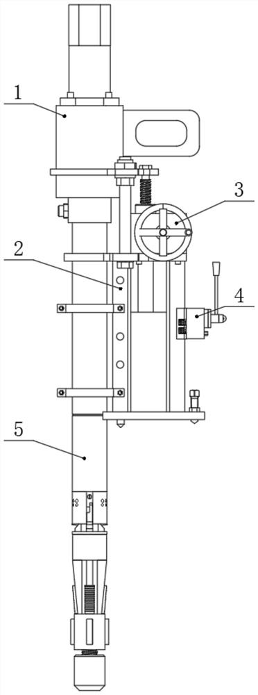
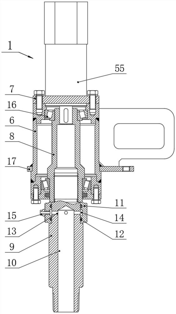
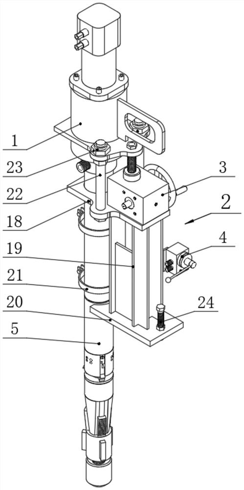
[0028] see figure 1 , the present invention provides a technical solution: the hydraulic pipe cutting machine for horizontal frozen pipes in the tunnel, including a frame 2, and guide rods 22 are fixedly connected to both sides of the top of the frame 2, and the surfaces of the guide rods 22 are slidably connected There is a sliding sleeve 23, the side of the sliding sleeve 23 is fixedly connected with the driving mechanism 1; connected; the bot...


PUM


Abstract

The invention discloses a hydraulic pipe cutting machine for horizontally frozen pipes in a tunnel, which includes a frame. Guide rods are fixedly connected to both sides of the top of the frame. The surface of the guide rod is slidably connected to a sliding sleeve. A drive mechanism is fixedly connected; a knife feed mechanism is fixedly connected in the middle of the top of the frame, and the end of the movable rod of the knife feed mechanism is fixedly connected with the drive mechanism; the bottom of the drive mechanism is connected with a mechanical inner knife mechanism. In the present invention, by setting the driving mechanism, the power of the driving mechanism is a hydraulic motor, the hydraulic motor is small in size, light in weight, impact-resistant, and the power output is relatively stable, which can provide a stable power source for the mechanical internal cutter mechanism, and the hydraulic motor only needs to cooperate Generally, the hydraulic pump station can be used, which is convenient for construction and movement in tunnels with small spaces, and the hydraulic pump station and the pipe cutter adopt a split structure. When operating, the hydraulic pump station is placed at the bottom of the tunnel, and only the cutting pipe needs to be moved. The machine can carry out pipe cutting machine operation.

Description

technical field [0001] The invention relates to the technical field of tunnel construction equipment. Specifically, it is a hydraulic pipe cutter for horizontally frozen pipes in tunnels. Background technique [0002] The horizontal freezing pipe is one of the important facilities in the freezing method construction. It can use artificial refrigeration technology to change the natural rock and soil into frozen soil, making it a water-stop curtain with high stability and strength; [0003] After the construction of the side channel structure is completed and the freezer is shut down, the gas flame cutting method is used for cutting the freezing hole at present, that is, the oxygen plus acetylene hand-held cutting torch is used. When cutting, the exposed orifice on the surface of the tunnel segment is cut first. tube and frozen tube, and then cut the frozen tube in the segment, and cut off the frozen tube in the segment by 60-80mm with a torch using a cutting torch (generally...

Claims


Application Information

Patent Timeline
Patent Type & Authority Patents(China)
IPC IPC(8): B23D21/14B23D21/04B23Q5/22B23Q11/10
CPCB23D21/14B23D21/04B23Q5/22B23Q11/10
Inventor 韩圣铭龚建宇付财李方政叶玉西高伟杨宁敖松韩玉福郑新赟
Owner BEIJING CHINA COAL MINE ENG CO LTD
Why Eureka
Try Eureka