A yag welding machine component that improves output energy stability in peak state

A technology of output energy and stability, which is applied in the field of YAG welding machine components, can solve the negative effects of output energy stability, YAG rod damage, melting and other problems, and achieve the effects of improving output energy stability, safe and reliable use, and avoiding false triggering

Active Publication Date: 2021-09-07
深圳镭锳激光科技有限公司
View PDF0 Cites 0 Cited by
  • Summary
  • Abstract
  • Description
  • Claims
  • Application Information

AI Technical Summary

Problems solved by technology

[0003] The YAG laser welding machine outputs laser light through the laser. The YAG laser is composed of a working substance (YAG rod), a pump lamp, an optical resonator and a cooling system. To ensure the welding quality and welding stability of the laser welding machine, it is necessary to control the laser. The stability of output energy, the factors that affect the stability of energy output of YAG welding machine include input energy, state of YAG rod and pump light source, etc. Among them, the damage of YAG rod will affect the stability of output energy. In the process of reaching the peak state , the temperature of the impurity inside the YAG rod suddenly rises to thousands of degrees, causing the volume expansion, melting and vaporization of the impurity itself, and then generating a large local stress around the impurity. Once these local stresses exceed the damage limit, they can cause YAG The destruction of the rod, which in turn negatively affects the stability of the output energy

Method used


Image

  • A yag welding machine component that improves output energy stability in peak state
  • A yag welding machine component that improves output energy stability in peak state
  • A yag welding machine component that improves output energy stability in peak state

Examples


Embodiment

[0029] as attached figure 1 to the attached Image 6 shown:

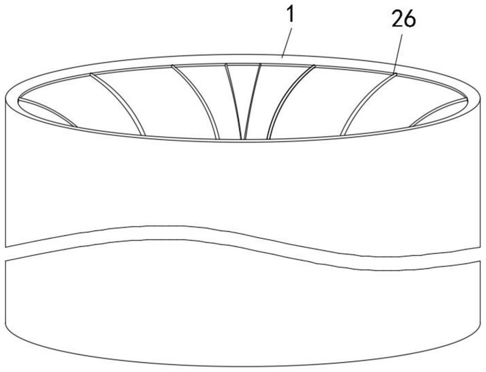
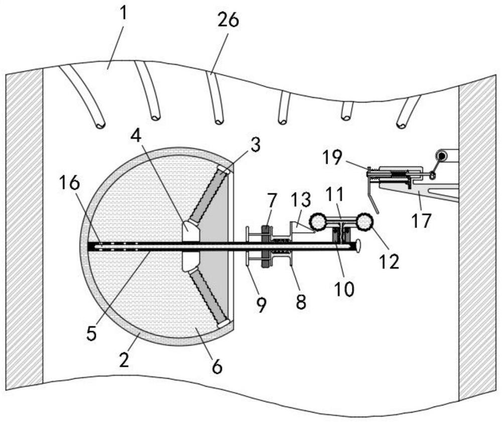
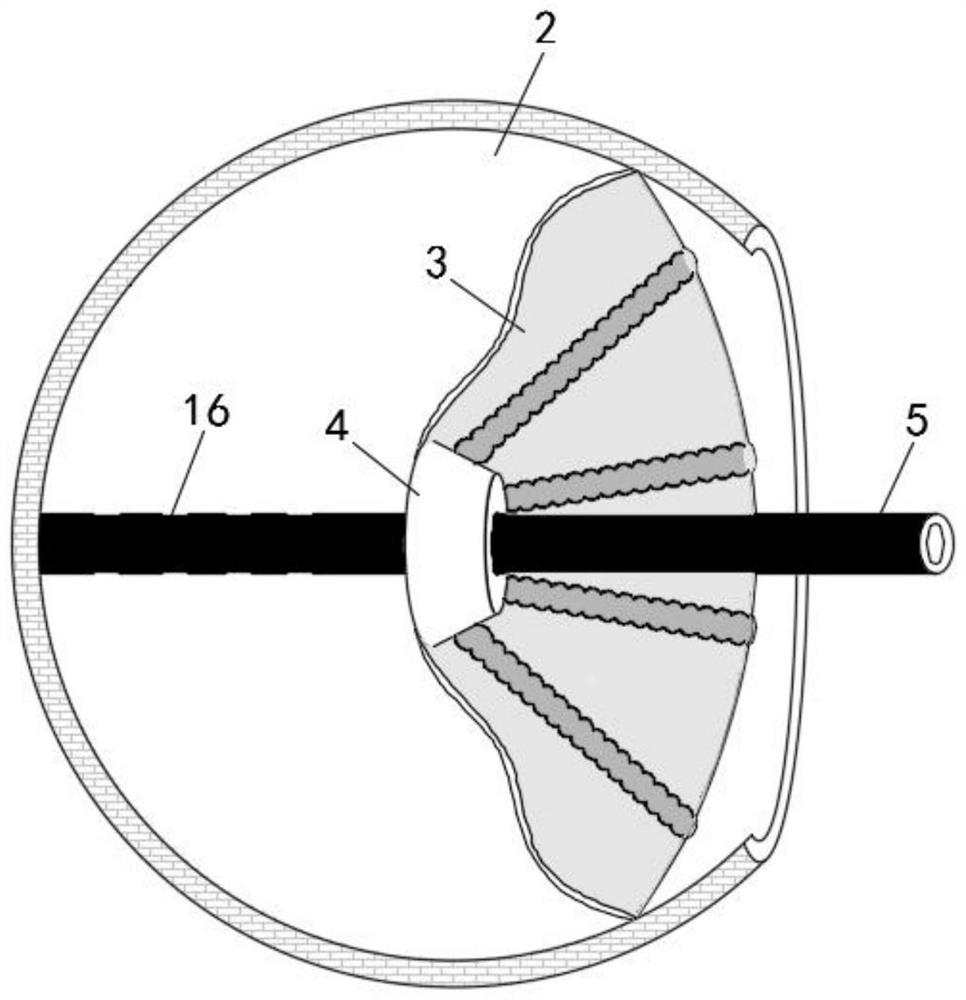
[0030] The present invention provides a YAG welding machine assembly for improving output energy stability in a peak state, comprising a rod tube sleeve 1, a heat conduction shell 2 is fixedly installed inside the rod tube sleeve 1, and an elastic sealing film 3 is installed on the right end of the heat conduction shell 2, A movable block 4 is arranged at the center of the elastic sealing film 3 , a fixed shaft 5 penetrating the movable block 4 is fixedly connected to the inner wall of the heat-conducting shell 2 , a detection liquid 6 is filled between the heat-conducting shell 2 and the elastic sealing film 3 , and the fixed shaft 5 The outer side and the right side of the elastic sealing membrane 3 is fixedly sleeved with a limit ring 7, the right side of the limit ring 7 is slidably installed with a sliding seat 8, and the left end of the sliding seat 8 is fixedly connected to the left side of the limit ring 7....


PUM


Abstract

The invention provides a YAG welding machine assembly which improves the stability of output energy in the peak state, which includes a rod tube sleeve, a fixed shaft penetrating through the movable block is fixedly connected to the inner wall of the heat conduction shell, and a penetrating to limit shaft is fixedly connected to the left end of the sliding seat. The strike plate on the left side of the ring, the right side of the sliding seat is fixedly connected with the wedge plate corresponding to the left telescopic balloon, the left end of the inner tube is fixedly connected with the push plate corresponding to the telescopic balloon on the left side of the support, and the support Elastic blocks corresponding to the tapered rings are movably plugged into the inner bottom wall of the inner bottom wall. When the YAG welding machine is about to reach the peak value, the internal temperature of the rod sleeve rises, and the vaporized volume of the detection liquid becomes larger, and the movable block is pushed to the right and collides with the impact plate, and the wedge plate squeezes the telescopic balloon to move upward, and the push plate squeezes the inserted The rod moves to the right, and the plunger drives the switch valve to rotate and open through the connecting rod, and the cooling liquid is passed into the cooling branch pipe to perform cooling in advance, which solves the problem that the temperature in the rod sleeve rises suddenly in the peak state, which leads to the damage of the YAG rod and affects the The problem of output energy stability.

Description

technical field [0001] The invention belongs to the technical field of YAG welding machines, and in particular relates to a YAG welding machine component which improves the stability of output energy in a peak state. Background technique [0002] YAG laser welding is to weld the workpiece with high-energy pulsed laser. It uses a pulsed xenon lamp as the pump source and ND:YAG as the working substance to generate the laser. The YAG laser welding machine has the advantages of small heat input, small heat affected zone, and workpiece shrinkage. It has the advantages of small deformation, easy to realize automatic welding, flexible control and fast welding speed. Therefore, the technical development and application of YAG laser welding will play a significant role in the development of the future manufacturing industry. [0003] The YAG laser welding machine outputs laser light through the laser. The YAG laser is composed of working material (YAG rod), pump lamp, optical resonat...

Claims


Application Information

Patent Timeline
Patent Type & Authority Patents(China)
IPC IPC(8): B23K26/21B23K26/70
CPCB23K26/21B23K26/70B23K26/702B23K26/703
Inventor 袁俊张高源张虎蒲亨强
Owner 深圳镭锳激光科技有限公司
Why Eureka
Try Eureka