Converter overvoltage protection system of unified power flow controller and parameter design method

A technology of a power flow controller and a protection system is applied to emergency protection circuit devices for limiting overcurrent/overvoltage, AC network circuits, emergency protection circuit devices, etc. The overvoltage protection level of the arrester is high, and the effect of ensuring safe and economical operation, reducing the overvoltage level of the converter and improving the reliability

Active Publication Date: 2021-06-22
NR ELECTRIC CO LTD +2
View PDF9 Cites 0 Cited by
  • Summary
  • Abstract
  • Description
  • Claims
  • Application Information

AI Technical Summary

Problems solved by technology

[0004] The existing overvoltage protection method for the converter of the unified power flow controller is to use a gapless zinc oxide arrester connected in parallel on the AC side of the converter and on the valve side of the series transformer, and the arrester connected in parallel on the valve side of the series transformer is also connected in parallel with a fast bypass switch , this protection method usually uses the voltage and current nonlinear characteristics of the zinc oxide arrester to limit the voltage between the converter valve terminals caused by the fault of the AC system, but the parameters of the gapless zinc oxide arrester in this method are controlled by the unified power flow. In the case of a DC side fault, The limitation of the overcurrent of the inverter and the high level of overvoltage protection of the arrester lead to a great increase in the manufacturing difficulty and cost of the inverter

Method used


Image

  • Converter overvoltage protection system of unified power flow controller and parameter design method
  • Converter overvoltage protection system of unified power flow controller and parameter design method
  • Converter overvoltage protection system of unified power flow controller and parameter design method

Examples


Embodiment Construction

[0031] The technical solutions and beneficial effects of the present invention will be described in detail below in conjunction with the accompanying drawings.

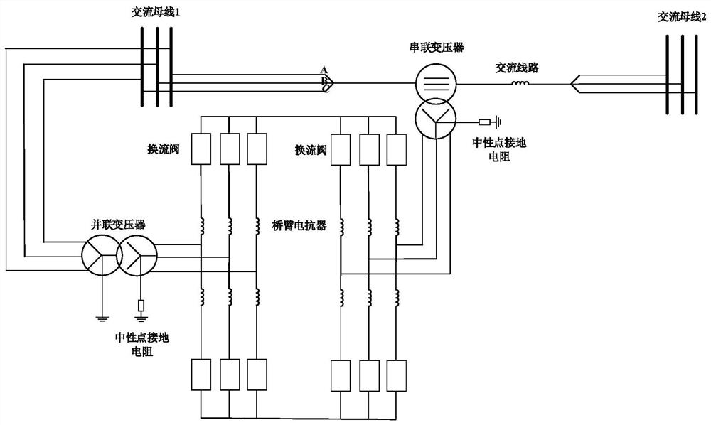
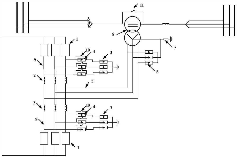
[0032] like figure 2 As shown, the present invention provides a converter overvoltage protection system for a unified power flow controller, which is suitable for figure 1 In the unified power flow controller shown, the converter is a three-phase six-leg structure, including a converter valve 1 and a bridge arm reactor 2. The converter valve 1 adopts a modular multi-level structure, and the sub-module adopts a half-bridge The sub-module; the converter is connected to the series transformer 8 through the copper bar 5, and the other end of the series transformer 8 is connected to the AC line.

[0033] The overvoltage protection system includes lightning arrester I 3, lightning arrester II 4, lightning arrester III 6, thyristor bypass switch 10, bypass circuit breaker 11 and monitoring device, wherein one end of lightn...


PUM

PropertyMeasurementUnit
Resistanceaaaaaaaaaa

Abstract

The invention discloses a converter overvoltage protection system of a unified power flow controller and a parameter design method. The system comprises a first lightning arrester, a second lightning arrester, a third lightning arrester, a thyristor bypass switch, a bypass circuit breaker and a monitoring device, wherein one end of the second lightning arrester is grounded through the first lightning arrester, and the other end of the second lightning arrester is connected to a connecting line between a converter valve and a bridge arm reactor; the thyristor bypass switch is connected with the second lightning arrester in parallel; the third lightning arrester is connected in parallel with the connecting copper bar in a star-shaped manner, and the neutral point of the third lightning arrester is connected with the neutral point of the series transformer and then grounded through a grounding resistor; the bypass circuit breaker is connected in parallel to the line side of the series transformer; and the monitoring module is used for monitoring and controlling the states of the converter valve, the thyristor bypass switch and the bypass circuit breaker, controlling the bypass thyristor to be conducted when detecting that the converter valve is locked, and simultaneously sending a closing command of the bypass circuit breaker. According to the technical scheme, the overvoltage protection level of the converter can be effectively reduced, and the economical efficiency and reliability of the converter are greatly improved.

Description

technical field [0001] The invention belongs to the field of flexible AC power transmission, and in particular relates to a converter overvoltage protection system for a unified power flow controller and a parameter design method thereof. Background technique [0002] The modern power system has gradually evolved into a large-scale AC-DC hybrid power grid. Problems such as unbalanced distribution of internal load and power generation in the power grid, and large differences in power flow distribution in transmission channels have become increasingly prominent. The problem of heavy and light loads in transmission channels exists at the same time. Limited by the bearing capacity of heavy-duty channels, the transmission channels in the power grid are difficult to be used very effectively. At the same time, due to the restrictions of urban planning, the difficulty of line reconstruction and power grid expansion is increasing day by day, and due to various conditions such as comp...

Claims


Application Information

Patent Timeline
IPC IPC(8): H02M1/32H02H9/04H02J3/00
CPCH02M1/32H02H9/04H02J3/00
Inventor 刘永刚陶风波王新宝谢天喜常宝立徐阳王真
Owner NR ELECTRIC CO LTD
Why Eureka
Try Eureka