Strap type back beater

A slapping device and strap-type technology, applied in the field of medical assistance, can solve problems such as the inability to adjust the order and strength of back slapping, poor phlegm-promoting effect, and small slapping range, so as to achieve the effect of increasing efficiency, saving time, and realizing disassembly

Active Publication Date: 2021-09-07
THE FIRST PEOPLES HOSPITAL OF CHANGZHOU
View PDF13 Cites 1 Cited by
  • Summary
  • Abstract
  • Description
  • Claims
  • Application Information

AI Technical Summary

Problems solved by technology

[0003] For example, the Chinese patent whose publication number is CN103655141B proposes an automatic slapping mechanism. The back slapping device is to hold the chair frame with both hands of the user, aim at the slapping part, and then start the motor after being aligned, and the rotating shaft of the motor will Start to drive the cam to rotate. When the cam continues to rotate, the roller will roll from the uphill section along the downhill section back to the low flat section. At this time, the roller will release the thrust on the rod, so that the rod will be supported by the elastic parts. The elastic force deflects to the slapping position P. As long as the user controls the continuous rotation of the cam, the rod will reciprocally sway between the slapping position P and the pre-pressing position P, and drive the slapping piece to repeat during the deflection process. The slapping action achieves the effect of slapping and promoting phlegm, but the slapping range of the back slapping device is small, and the order and strength of the back slapping cannot be adjusted, so the effect of sputum promoting is poor. At the same time, many patients cannot get out of bed or sit on the slapping device expectoration, in order to solve the above problems we propose a strap-type back slapper

Method used


Image

  • Strap type back beater
  • Strap type back beater
  • Strap type back beater

Examples


Embodiment Construction

[0041] The following will clearly and completely describe the technical solutions in the embodiments of the present invention with reference to the accompanying drawings in the embodiments of the present invention. Obviously, the described embodiments are only some, not all, embodiments of the present invention. Based on the embodiments of the present invention, all other embodiments obtained by persons of ordinary skill in the art without making creative efforts belong to the protection scope of the present invention.

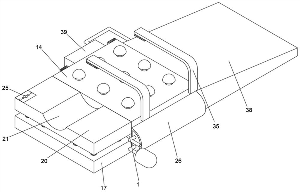
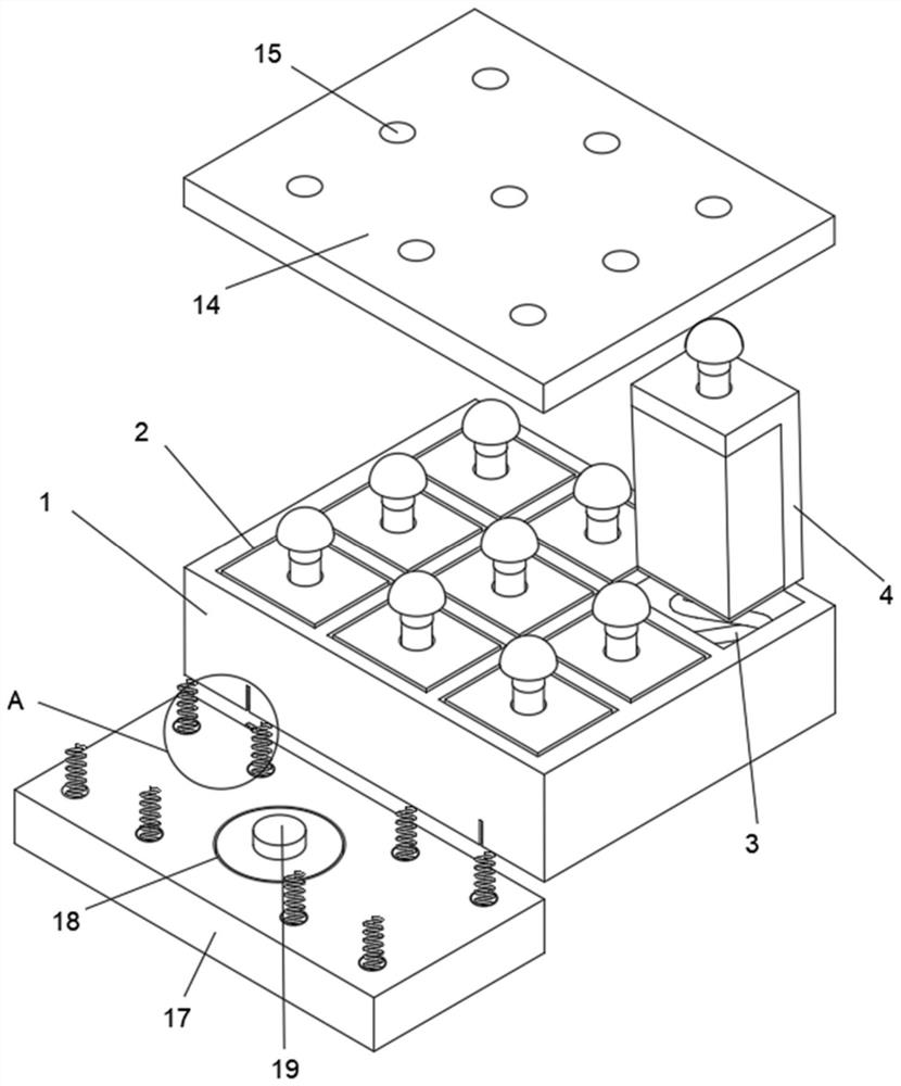
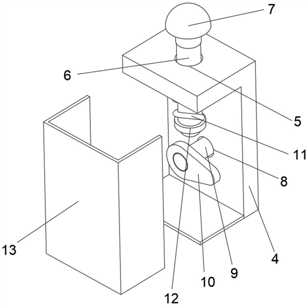
[0042] refer to figure 1 with figure 2 with image 3 with Figure 4 , strap-type back slapper, comprising a slapping box 1, the top surface of the slapping box 1 is provided with several instrument grooves 2, the bottom surface of the instrument groove 2 is fixedly equipped with a first spring 3, and the inside of the instrument groove 2 is provided with a slapping frame 4, wherein The bottom surface of the beater frame 4 is fixedly connected with the firs...


PUM


Abstract

The invention discloses a strap type back beater, and the main points of the technical solution are: the strap type back beater comprises a beating box, a plurality of instrument grooves are formed in the top face of the beating box, and first springs are fixedly installed on the bottom faces of the instrument grooves; a beating frame, the beating frame is arranged in the instrument groove, the bottom surface of the beating frame is fixedly connected with the first spring, a telescopic hole is formed in the top surface of the beating frame, a telescopic column is movably sleeved inside the telescopic hole, and a beating massage head is fixedly installed on the top surface of the telescopic column; a rotating groove, the rotating groove is formed in one side of the beating frame, a driving motor is fixedly sleeved inside the rotating groove, and a cam block is fixedly sleeved on the outer circle wall face of a rotating shaft of the driving motor; the driving motor is started to drive the cam block to rotate, the telescopic column is extruded through the cambered surface of the cam block, the effect of continuously extruding the telescopic column is achieved, and the effect of driving the beating massage head to sequentially beat the back of a patient and promoting sputum is achieved.

Description

technical field [0001] The invention relates to the technical field of medical assistance, in particular to a strap-type back slapper. Background technique [0002] We all know that whether it is a cold or a fever, it will eventually be accompanied by a cough. Adults who have a cold, fever or even a cough can recover quickly, while the elderly and children have weaker resistance and recover slowly. The reason why the cough does not get better is because There is still sputum in the lungs, and the cough can only be relieved by clearing the sputum. Atomization is to disperse the drug into tiny mist or particles, suspend it in the gas, and enter the respiratory tract and lungs to achieve humidification. Airway, for the purpose of treating inflammation of the respiratory tract. [0003] For example, the Chinese patent whose publication number is CN103655141B proposes an automatic slapping mechanism. The back slapping device is to hold the chair frame with both hands of the user...

Claims


Application Information

Patent Timeline
Patent Type & Authority Applications(China)
IPC IPC(8): A61H23/02A61M1/00A61M11/00A61M31/00
CPCA61H23/02A61H23/006A61M11/00A61M31/00A61H2201/1207A61H2205/081
Inventor 郭小燕
Owner THE FIRST PEOPLES HOSPITAL OF CHANGZHOU
Why Eureka
Try Eureka