Echo detection multi-tube laser conduction illumination system

A technology of echo detection and lighting system, applied in the field of lighting, can solve the problems of incomplete energy release, fire surrounding substances, lighting system damage, etc., and achieve the effect of improving light output efficiency, saving construction costs, and reducing the number of optical fibers

Pending Publication Date: 2021-09-07
重庆云创江来光电科技有限公司
View PDF0 Cites 0 Cited by
  • Summary
  • Abstract
  • Description
  • Claims
  • Application Information

AI Technical Summary

Problems solved by technology

[0003]Laser light transmission lighting mainly uses light transmission. Since the optical fiber is made of silica fiber with a small core, the optical fiber may break under the action of external force. After the optical fiber breaks, the entire lighting is in a state of no lighting. If the power is not cut off in time, the light of a specific wavelength will be on for a long time at the broken position, and the broken position is in a closed state, and the energy cannot be fully released. If the heat reaches a certain level, it will cause damage to the entire lighting system, and if the heat is too high, it will cause fire or damage to surrounding materials

Method used


Image

  • Echo detection multi-tube laser conduction illumination system
  • Echo detection multi-tube laser conduction illumination system
  • Echo detection multi-tube laser conduction illumination system

Examples


Embodiment 1

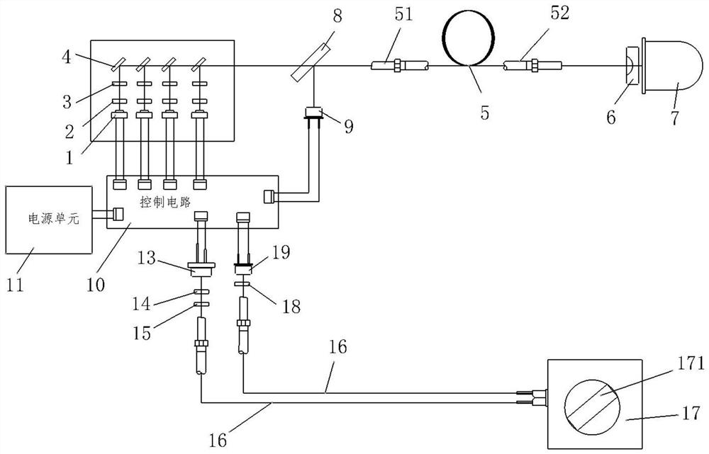
[0045] as attached figure 2 Shown: the first passive switch includes a first infrared LD13, a second collimating lens 14, a first coupling lens 15, a second transmission fiber 16, a first switching unit 17, a second coupling lens 18 and a second photoelectric element PD19 The red light irradiated by the first infrared LD13 enters the second transmission fiber 16 through the second collimating lens 14, the first coupling lens 15, and is transmitted to the first switch unit 17 through the second transmission fiber 16, and the first switch unit 17 is provided with a first reflective mirror 171, by adjusting the angle of the first reflective mirror 171 to control whether the red light of the first infrared LD 13 is reflected on the second photoelectric element PD 19; when the second photoelectric element PD 19 receives the first When the red light of an infrared LD 13 is on, the first passive switch 17 is in the on state, and when the second photoelectric element PD 19 cannot rec...

Embodiment 2

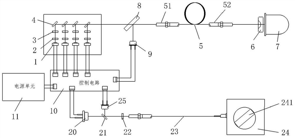
[0047] as attached image 3 Shown: the second passive switch includes a second infrared LD 20, a second filter system 21, a third coupling lens 22, a third transmission fiber 23, a second switch unit 24 and a third photoelectric element PD25; the second infrared LD20 The irradiated red light from the second filter system 21 and the third coupling lens 22 enters the third transmission fiber 23, and is transmitted to the second switch unit 24 through the third transmission fiber 23, and the second switch unit 24 is provided with a second Reflective mirror 241 controls whether the red light of the second infrared LD20 is reflected on the third photoelectric element PD25 by adjusting the angle of the second reflective mirror 241; when the third photoelectric element PD25 received the red light of the second infrared LD20, the second The second passive switch is in the open state, and when the third photoelectric element PD25 cannot receive the red light of the second infrared LD20...

Embodiment 3

[0050] The manual power switch 26 realizes the power-off and power supply of the echo detection multi-tube laser conduction lighting system of the present invention through the opening and closing of the manual control switch system, as attached Figure 4 .


PUM

PropertyMeasurementUnit
Thicknessaaaaaaaaaa
Lengthaaaaaaaaaa
Diameteraaaaaaaaaa

Abstract

The invention belongs to the technical field of illumination, and particularly discloses an echo detection multi-tube laser conduction illumination system, which comprises a multi-tube laser conduction illumination system, an echo detection system, a control circuit, a power supply unit and a switch system, optical fiber conduction is adopted, photoelectric separation is achieved, and lighting safety is improved; transmission-type excitation is adopted, so that the luminous efficiency is improved, the service life of the blue light LD is prolonged, and the safety is also improved; a plurality of blue-light LDs are adopted, so that the single-fiber energy can be effectively improved, the number of optical fibers is reduced, and the construction cost is saved; echo blue light detection is adopted, and a light filtering system is adopted at the incident end of a transmission optical fiber, so that reflected blue light is effectively transmitted to a photoelectric element PD, the light emitting condition can be monitored in time, and the safety is improved; and the switch system adopts a passive remote switch technology, realizes a non-electric control system, and is safer and more convenient to use.

Description

technical field [0001] The invention belongs to the technical field of illumination, and in particular relates to an echo detection multi-tube laser conduction illumination system. Background technique [0002] Traditional lighting mainly adopts the method of arranging electricity in the area that needs to be illuminated, and then converts the electrical energy into light through a photoelectric conversion chip, and then performs lighting after photoelectric conversion. This kind of lighting is easy to cause safety accidents because the photoelectric conversion is in the lighting area, while laser light Conducted lighting mainly uses remote photoelectric conversion, and then transmits the light of a specific wavelength to the place where it needs to be applied through an optical fiber, and then converts the light of a specific wavelength into the required white light through phosphor technology, so as to achieve no electricity in the use area. , to achieve photoelectric sepa...

Claims


Application Information

Patent Timeline
IPC IPC(8): F21S8/00F21V8/00F21V9/30F21V9/32F21V5/04G02B6/26F21V23/04G01J1/42G01J1/04F21Y115/30
CPCF21S8/00F21V9/30F21V9/32F21V5/048F21V23/04G02B6/262G01J1/42G01J1/0411F21V2200/10F21V2200/13F21Y2115/30G01J2001/4247
Inventor 刘浪侯杰
Owner 重庆云创江来光电科技有限公司
Why Eureka
Try Eureka