Energy storage device

An energy storage device and energy storage technology, which is applied in the substation/distribution device casing, substation/switchgear cooling/ventilation, anti-vibration equipment, etc. Large resistance and other problems, to improve safety and service life, and prevent rapid falling

Active Publication Date: 2022-06-21
无锡海克赛德热能科技有限公司
View PDF7 Cites 0 Cited by
  • Summary
  • Abstract
  • Description
  • Claims
  • Application Information

AI Technical Summary

Problems solved by technology

[0002]At present, the thermal conductivity of energy storage materials is low, the thermal conduction resistance is large, and the heat transfer and absorption in short-term transient conditions are slow, resulting in heat accumulation and deriving temperature rise. Moreover, the energy storage device is dangerous. When the energy storage device encounters vibration or collision, it is easy to damage the components inside, and the risk is high.
Moisture problems will appear outside the energy storage device for a long time, which will affect the energy in the energy storage device. If the energy storage device is left for a long time, it will be covered with dust, and the dust will rust the contact points of the energy storage box, which in turn will affect the Normal use of energy storage devices

Method used


Image

  • Energy storage device
  • Energy storage device
  • Energy storage device

Examples


Embodiment Construction

[0026] The technical solutions in the embodiments of the present invention will be clearly and completely described below with reference to the accompanying drawings in the embodiments of the present invention. Obviously, the described embodiments are only a part of the embodiments of the present invention, but not all of the embodiments.

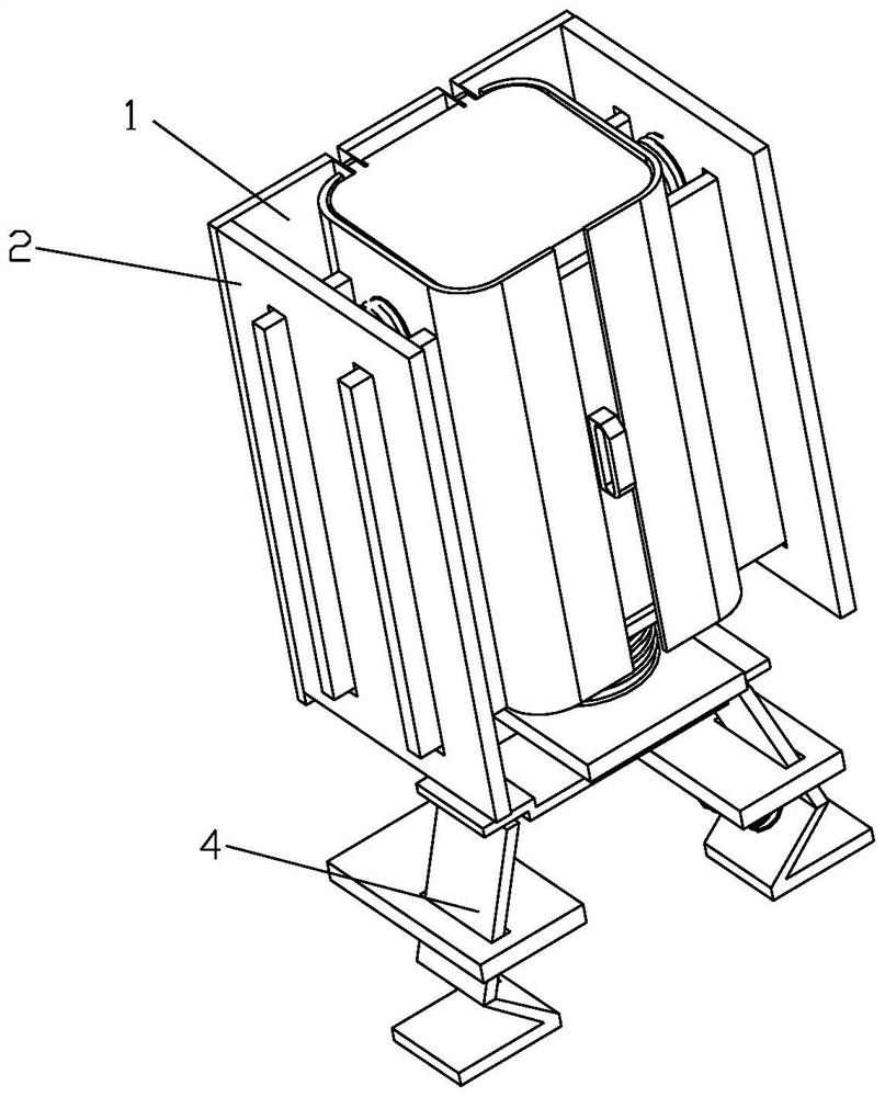
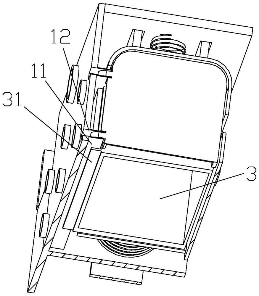
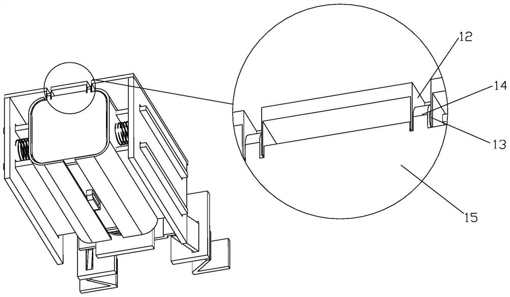
[0027] Attached below Figure 1-6 The present invention is further described with examples:

[0028] In this embodiment, as Figure 1-6 As shown, an energy storage device includes a support plate 1, a sliding portion 11 is connected to the outer surface of one side of the support plate 1, and a rotation groove 12 is provided on the upper end surface of the support plate 1, and the rotation groove 12 is connected by a rotating shaft 13. There is a rotating part 14, one side of the rotating part 14 is connected with a cover plate 15, a accommodating cavity 16 is opened on the lower end surface of the cover plate 15, and a protective mechanis...


PUM


Abstract

An energy storage device comprises a supporting plate, the outer surface of one side of the supporting plate is connected with a sliding part, the upper end face of the supporting plate is provided with a rotating groove, the rotating groove is connected with a rotating part through a rotating shaft, one side of the rotating part is connected with a cover plate, the lower end face of the cover plate is provided with a containing cavity, and the two sides of the outer surface of the supporting plate are connected with protection mechanisms. When the suction cup is used, a place with good ventilation can be selected for wall suction fixing, ventilation can be performed through the containing cavity in the cover plate after the suction cup is fixed and the energy storage box is placed, and due to the fact that after the cover plate covers the energy storage box, the containing cavity cannot abut against the upper end face of the energy storage box, a small space can be reserved, and ventilation can be performed through the small space. And the ventilation requirement is favorably improved.

Description

technical field [0001] The invention relates to the technical field of energy storage devices, in particular to an energy storage device. Background technique [0002] At present, the thermal conductivity of energy storage materials is low, the thermal conduction resistance is large, and the heat transfer and absorption under short-term transient conditions are slow, resulting in heat accumulation and deduction of temperature rise. Moreover, the energy storage device is dangerous to a certain extent, and the energy storage device encounters vibration. Or when it collides, it is easy to damage the components inside, and the risk is higher. For a long time outside the energy storage device, there will be moisture problems, which will affect the energy in the energy storage device. If the energy storage device is placed for a long time, it will be covered with dust, and the dust will cause rust on the contact points of the energy storage box, which will affect the Normal use o...

Claims


Application Information

Patent Timeline
Patent Type & Authority Applications(China)
IPC IPC(8): H02B1/56H02B1/28H02B1/54H02B1/26
CPCH02B1/56H02B1/28H02B1/54H02B1/26Y02E60/10
Inventor 陈以春韩志鹏
Owner 无锡海克赛德热能科技有限公司
Why Eureka
Try Eureka