Composite pressure reduction type hydrogen energy pressure reducing valve

A pressure reducing valve, hydrogen energy technology, applied in the direction of functional valve type, lifting valve, balance valve, etc., can solve the problems such as the dynamic and stable adjustment ability needs to be improved, the damage of the hydrogen energy pressure reducing valve is large, and the pressure reduction effect needs to be improved. Achieve the effect of automatic adjustment, constant gas pressure and simple structure

Pending Publication Date: 2022-07-29
南京吴中自控工程有限公司
View PDF0 Cites 2 Cited by
  • Summary
  • Abstract
  • Description
  • Claims
  • Application Information

AI Technical Summary

Problems solved by technology

[0004] At present, the conventional hydrogen energy pressure reducing valve is composed of many scattered functional components such as a filter, a pressure reducing valve, a low pressure sensor, an unloading valve, a manual stop valve, and a one-way valve. The structure is complex, the inlet flow rate is fast, and the pressure reducing effect needs to be improved. Great damage to the hydrogen energy pressure reducing valve
In addition, the existing hydrogen energy pressure reducing valve, in the process of use, needs to be improved in terms of dynamic and stable regulation.

Method used


Image

  • Composite pressure reduction type hydrogen energy pressure reducing valve
  • Composite pressure reduction type hydrogen energy pressure reducing valve
  • Composite pressure reduction type hydrogen energy pressure reducing valve

Examples


Embodiment Construction

[0028] The present invention will be further described below in conjunction with specific embodiments.

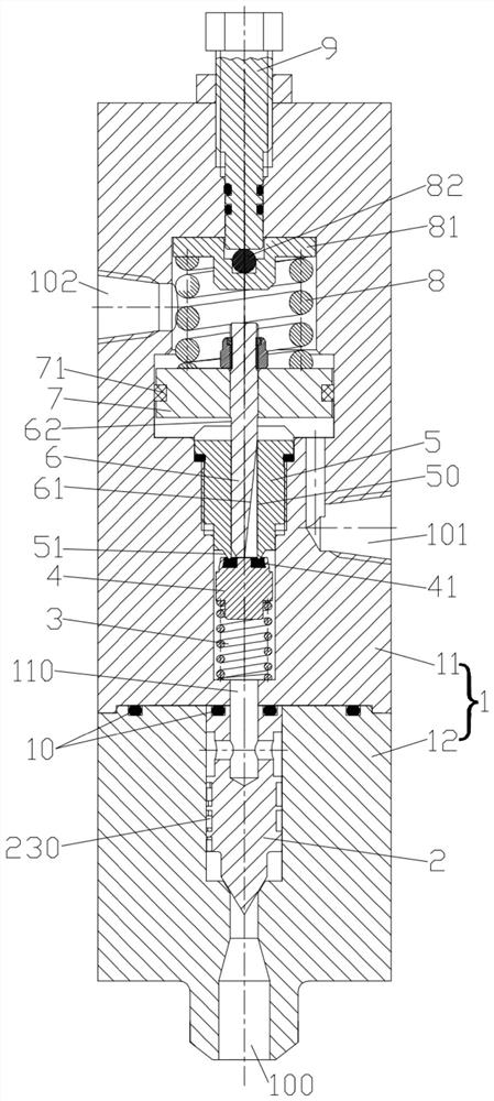
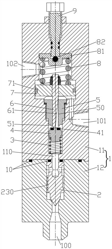
[0029] like figure 1 and 2 As shown in the figure, a compound pressure-reducing type hydrogen energy pressure reducing valve according to an embodiment of the present invention includes a valve body 1, the valve body 1 has a medium inlet 100 and a medium outlet 101, and a needle valve core is arranged at the medium inlet 100 2.

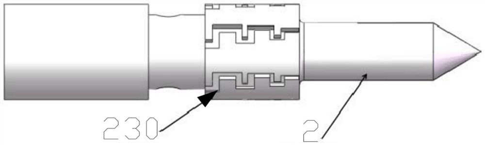
[0030] like image 3 and 4 As shown, the needle valve core 2 is a columnar structure, and the needle valve core 2 is divided into five sections according to the external dimensions, which are called the first section 21, the second section 22, the third section 23, and the fourth section 24 from bottom to top. and fifth paragraph 25. The first section 21 is the lower top of the needle valve core 2, which adopts a conical surface structure, and there is a gap between the conical surface structure and the valve body 1 for the medium to pass thro...


PUM


Abstract

The invention discloses a composite depressurization type hydrogen energy source pressure reducing valve which comprises a valve body with a medium inlet and a medium outlet, a needle-shaped valve element is arranged at the medium inlet and provided with a plurality of wedge-shaped throttling channel notches, a first hedging flow channel is formed in the needle-shaped valve element and communicated with the wedge-shaped throttling channel notches through side flow channels, and a second hedging flow channel is formed in the needle-shaped valve element and communicated with the wedge-shaped throttling channel notches through side flow channels. A second hedging flow channel communicated with the first hedging flow channel is arranged in the valve body, a guide cylinder is arranged in the valve body, the guide cylinder is provided with a push rod via hole and a push rod capable of reciprocating, the push rod is provided with a wedge-shaped notch, a cut-off piece is arranged below the guide cylinder, after the push rod moves downwards, a gap is formed between the cut-off piece and the lower end of the guide cylinder, and a lower spring is arranged between the cut-off piece and the second hedging flow channel. The push rod is sleeved with a piston, an upper spring in the valve body abuts against the piston, the valve body is provided with a constant-pressure gas inlet, and the valve body is provided with an adjusting nut acting on the upper spring. The flow resistance is increased, the flow speed is controlled, the pressure is reduced through the needle-shaped valve element of a special structure, the pressure at the medium outlet is constant, and the pressure stabilizing effect is good.

Description

technical field [0001] The invention relates to the technical field of a pressure reducing valve for industrial automation control, and more particularly to a compound pressure reducing type hydrogen energy pressure reducing valve. Background technique [0002] At present, the most important energy sources in the world are fossil energy, mainly petroleum, coal and natural gas. These fossil energy have the characteristics of non-renewable, high pollution, low energy conversion efficiency, and combustion of greenhouse gases. At present, the energy demand of all countries in the world is increasing, and the reserves of fossil energy are decreasing. Therefore, in the future development of the industrial society, the use of clean and efficient new energy will become a further demand. Hydrogen is a kind of new energy. [0003] High-pressure hydrogen has strong corrosiveness and large temperature changes during high-pressure decompression, which may cause hydrogen corrosion, hydrog...

Claims


Application Information

Patent Timeline
Patent Type & Authority Applications(China)
IPC IPC(8): F16K17/28F16K47/08F16K27/02F16K1/36
CPCF16K17/28F16K47/08F16K27/02F16K1/36
Inventor 王玮杜翔王珲马小军王瑞
Owner 南京吴中自控工程有限公司
Why Eureka
Try Eureka