Supercharge Your Innovation With Domain-Expert AI Agents!

Electromagnetic drive

An electromagnetically driven and driven technology, applied to electromagnets, electromagnets with armatures, circuits, etc., can solve the problem that the old solenoid device 100 cannot fully adapt to the miniaturization of lens barrels or cameras

Inactive Publication Date: 2005-07-20
OLYMPUS OPTICAL CO LTD
View PDF0 Cites 0 Cited by
  • Summary
  • Abstract
  • Description
  • Claims
  • Application Information

AI Technical Summary

Problems solved by technology

If the above-mentioned solenoid device 100 needs to be arranged between the inner circumference of the lens frame 111 and the outer diameter portion of the photographic lens 112, then the outer diameter D0 of the lens frame that determines the outer diameter of the lens barrel 110 cannot be smaller than the specified size, and the old-fashioned spiral Tube device 100 does not adequately accommodate lens barrel or camera miniaturization

Method used


Image

  • Electromagnetic drive
  • Electromagnetic drive
  • Electromagnetic drive

Examples


Embodiment Construction

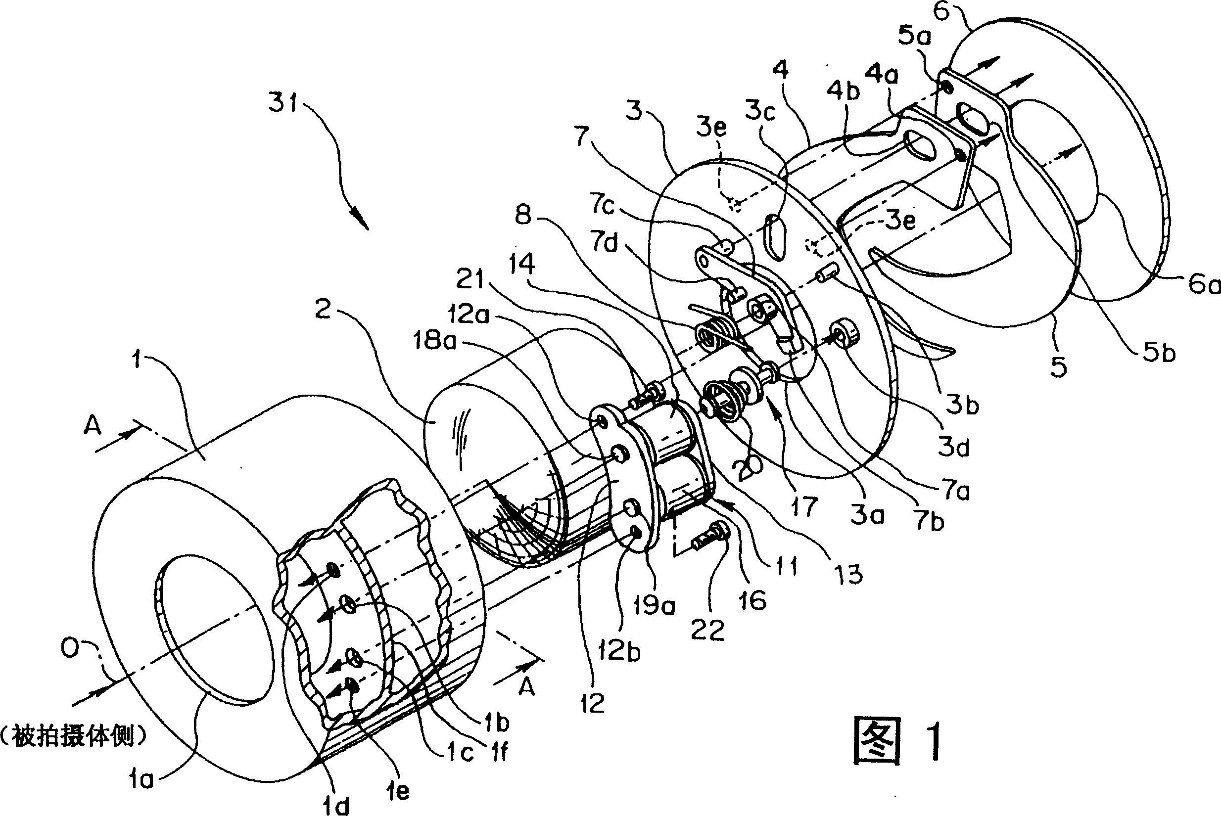
[0029] Embodiments of the present invention will be described in detail below using the drawings.

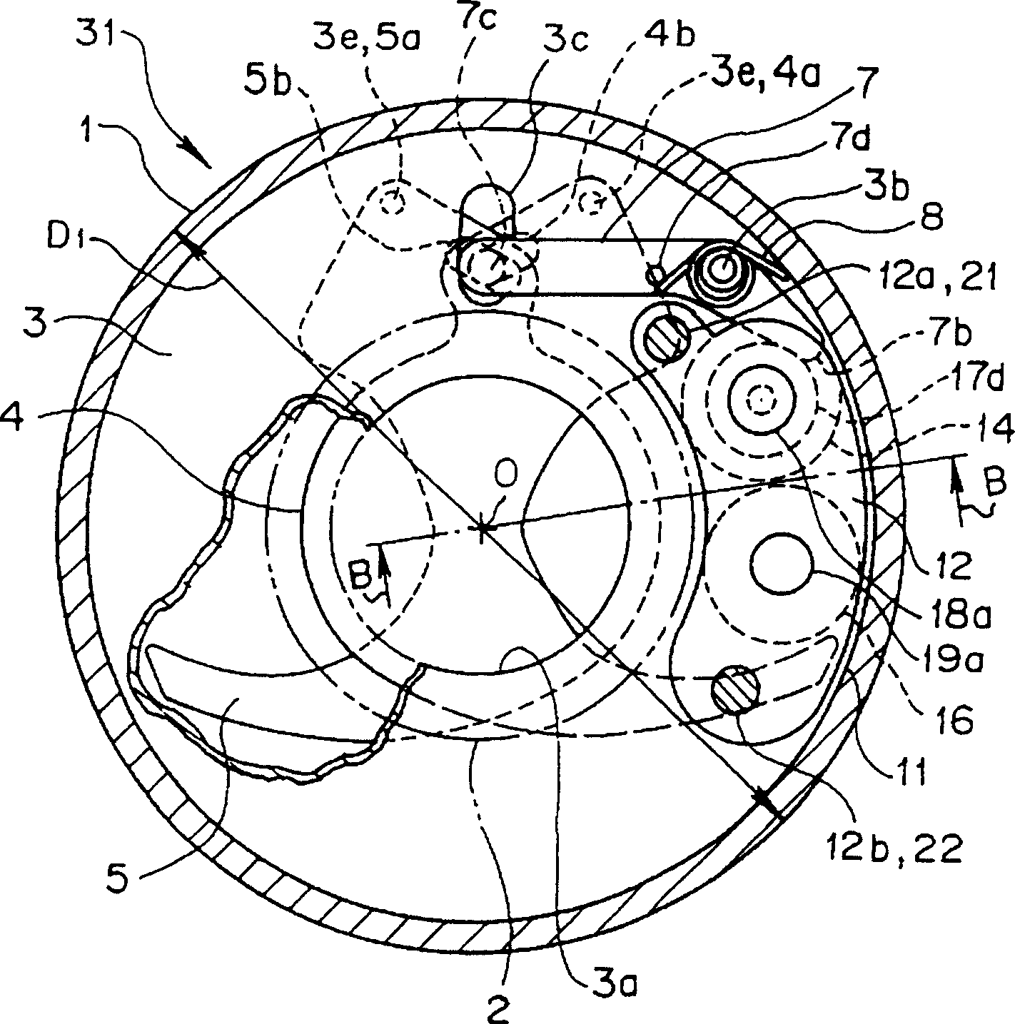
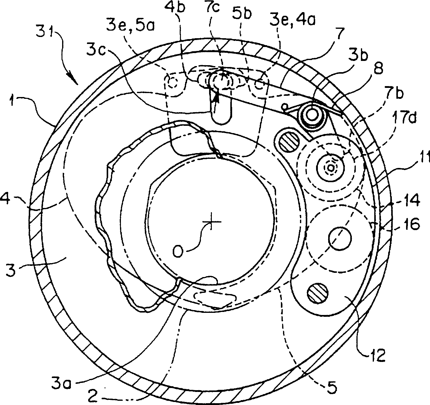
[0030] Fig. 1 is an exploded perspective view of a lens barrel according to a first embodiment of the present invention, in which an electromagnetic drive device for exposure control is assembled. figure 2 , 3 It is the A-A sectional view of Fig. 1, figure 2 Indicates that the shutter blades are closed, image 3 Indicates the shutter blade open state. Figure 4 yes figure 2 The B-B cross-sectional view. Figure 5 It is a figure which looked at the said electromagnetic drive device from the protruding surface side of a plunger. Figure 6 yes Figure 5 The C-C sectional view of , which shows the protruding state of the plunger core. Figure 7 yes Figure 6 F direction view. Figure 8 yes Figure 6 Enlarged view of part D of . Figure 9 yes Figure 6 Enlarged view of part E. In addition, in the following description, the turning direction is indicated by the turning...


PUM


Abstract

The invention provides an electromagnetic driving device being capable of effectively utilizing a disposal space and having an effect for compacting assembled equipment. A DC solenoid device as the electromagnetic driving device applied for controlling the exposure of a lens barrel has coils as two solenoids pinched by yokes, and a retractable plunger (a moving core)is inserted into the hollow section of the coil. The plunger is attracted and repulsed by a magnetic circuit formed of magnetic flux generated by the coils, and shutter blades are opened and closed. The outside diameters of the coils can be made smaller than that of a single coil in a conventional solenoid device, the disposal space of the solenoid device is reduced, and the electromagnetic driving device has an effect for miniaturizing the lens barrel.

Description

technical field [0001] The invention relates to a structure of an electromagnetic driving device with a movable iron core and a solenoid. Background technique [0002] In the past, the driving source of the exposure control device of the camera used an electromagnetic drive device with a movable iron core (rod core) and a solenoid, that is, a DC solenoid plunger core (hereinafter referred to as the solenoid device) . For example, in the exposure control device of the conventional camera lens barrel shown in the sectional view of FIG. Figure 19 An old-fashioned electromagnetic control device of the structure shown in the cross-sectional view. [0003] The above-mentioned old-fashioned lens barrel 110 has a taking lens 112 supported by a lens frame 111, and an aperture portion 111a is provided behind the taking lens of the lens cabinet 111. Around the aperture portion 111a, two shutter blades 113, 114 are rotatably supported by support pins 117b, 117a. The shutter blades 1...

Claims


Application Information

Patent Timeline
Patent Type & Authority Patents(China)
IPC IPC(8): G03B9/10G03B9/08G03B9/26H01F5/00H01F7/06H01F7/16
Inventor 片桐护八高桥敬太
Owner OLYMPUS OPTICAL CO LTD
Features
  • R&D
  • Intellectual Property
  • Life Sciences
  • Materials
  • Tech Scout
  • Unparalleled Data Quality
  • Higher Quality Content
  • 60% Fewer Hallucinations
Learn More