Micro-path parallel current heat-exchanger for transcritical Co2 circulation and mfg. method

A technology of parallel flow heat exchanger and manufacturing method, applied in the direction of heat exchanger type, indirect heat exchanger, lighting and heating equipment, etc., can solve the problem that the welding quality is not easy to control, the yield of heat exchanger is reduced, and the temperature is uneven. and other problems, to achieve the effects of easy control of welding quality, improved yield and uniform heating

Active Publication Date: 2007-08-22
TSINGHUA UNIV +1
View PDF5 Cites 0 Cited by
  • Summary
  • Abstract
  • Description
  • Claims
  • Application Information

AI Technical Summary

Problems solved by technology

However, the 8-shaped double-tube header or four-tube header has fluctuations in the shape of the arc surface, and the solder is not easy to adhere to the surface to be welded, and the welding of the header and the flat tube bundle is difficult. Difficult; the temperature will also be locally uneven during the welding process, and the welding quality is not easy to control
As the number of parallel tube bundles increases, the yield of the heat exchanger decreases significantly

Method used


Image

  • Micro-path parallel current heat-exchanger for transcritical Co2 circulation and mfg. method
  • Micro-path parallel current heat-exchanger for transcritical Co2 circulation and mfg. method

Examples


Embodiment Construction

[0021] The structure and manufacturing method of the present invention will be further described below in conjunction with the accompanying drawings.

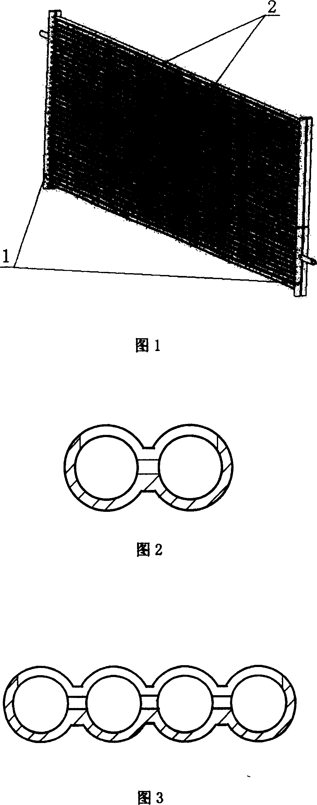
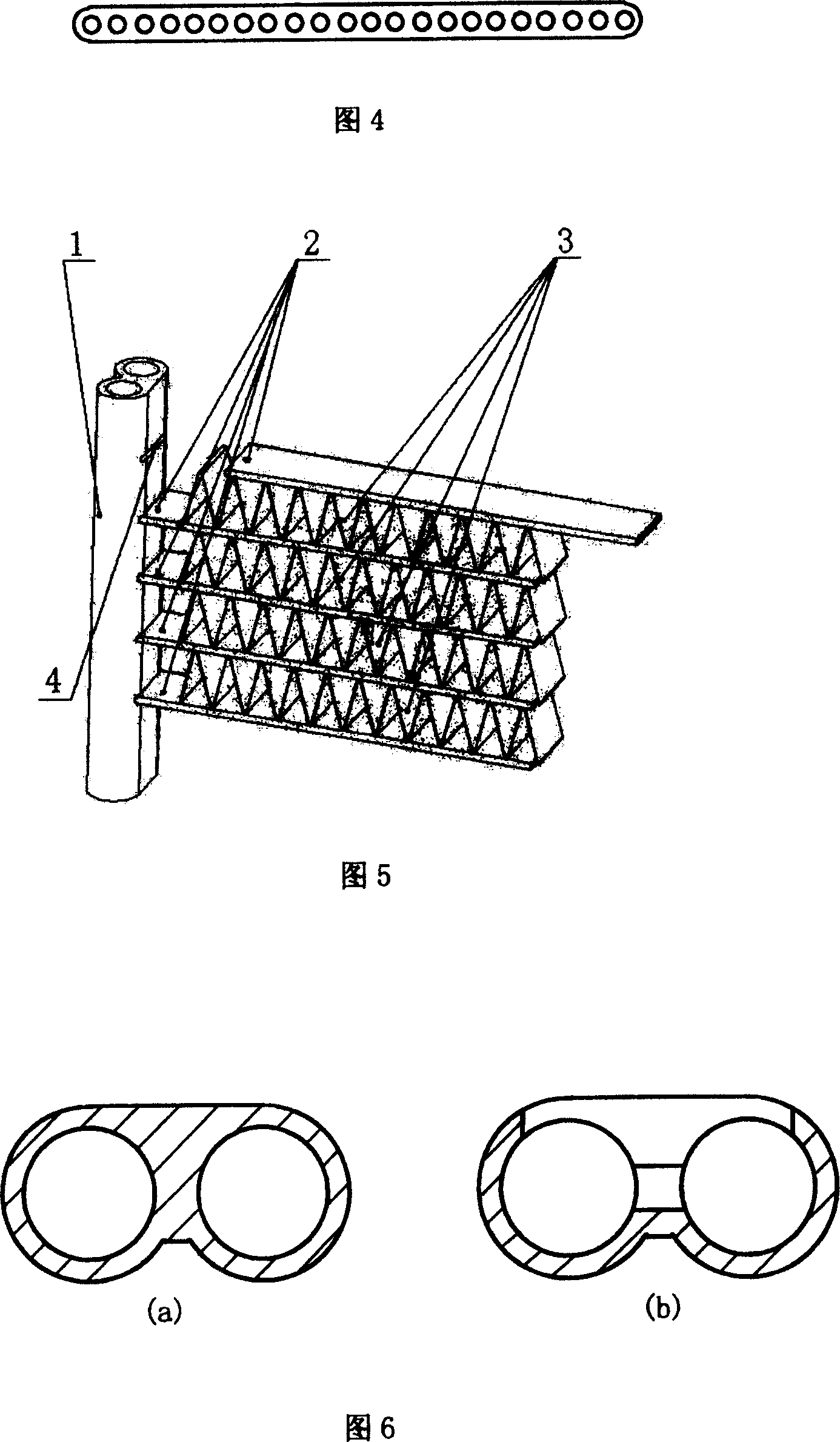
[0022] Fig. 5 is a schematic diagram of the three-dimensional structure of the microchannel parallel flow heat exchanger provided by the present invention. The microchannel parallel flow heat exchanger contains a multi-tube header 1, and a heat exchange flat tube bundle 2 welded between the two headers. Fins 3 are welded between the parallel flat tube bundles. Fig. 6 a is the schematic cross-sectional structure diagram of the multi-barrel header provided by the present invention, one side of which is designed as a plane and formed by extrusion; in order to be welded with flat tube bundles, mill out parallel tubes with flat tube thickness and width on the welding plane Heat exchange flat tube tank 4 (Fig. 6b).

[0023] CO 2 The working medium first enters the multi-tube header 1 (inlet header) on one side of the heat exchanger...


PUM


Abstract

A method for preparing microchannel and parallel flow exchanger for transcritical CO2 circulation includes extrusion - moulding collector tube in multi-tube structure and heat exchanging flat tube separately to let one side of multi-tube collector tube be planar structure, making parallel slots for heat exchanging flat tubes on planar side of multi-tube collector tube, using weld flux to cover the part of the flat tube to be welded and applying vacuum one - body brass soldering for finishing .

Description

technical field [0001] The present invention relates to a method for CO 2 The invention relates to a micro-channel parallel flow heat exchanger in a transcritical vapor compression refrigeration and heat pump device as a working medium, and specifically relates to a gas cooler or an evaporator used in a refrigeration and heat pump device. Background technique [0002] in CO 2 Among the heat exchangers used in transcritical cycle refrigeration and heat pump devices, one of the heat exchangers works on the high-pressure side of the system, and supercritical CO 2 The heat is released and cooled in the tube of the heat exchanger, and the pressure can reach above 10MPa. The ambient air heats up through the fins outside the tube. This heat exchanger is called a gas cooler; the other heat exchanger works on the low-pressure side of the system. Subcritical CO 2 The heat is absorbed and evaporated in the heat exchanger tube, the pressure is about 4MPa, and the heat is exchanged wi...

Claims


Application Information

Patent Timeline
Patent Type & Authority Patents(China)
IPC IPC(8): F28D1/03B23P15/26
Inventor 邓建强李建明姜培学
Owner TSINGHUA UNIV
Why Eureka
Try Eureka