

Cyclone cooling method and cooling tower
A cooling method and cooling tower technology, applied in water shower coolers, direct contact heat exchangers, heat exchanger types, etc., can solve the problems of small heat exchange area, low heat dissipation efficiency, small specific surface area, etc., and achieve High heat dissipation efficiency, improved utilization rate, and high heat dissipation intensity
- Summary
- Abstract
- Description
- Claims
- Application Information
AI Technical Summary
Problems solved by technology
Method used
Image

Examples
Embodiment 1
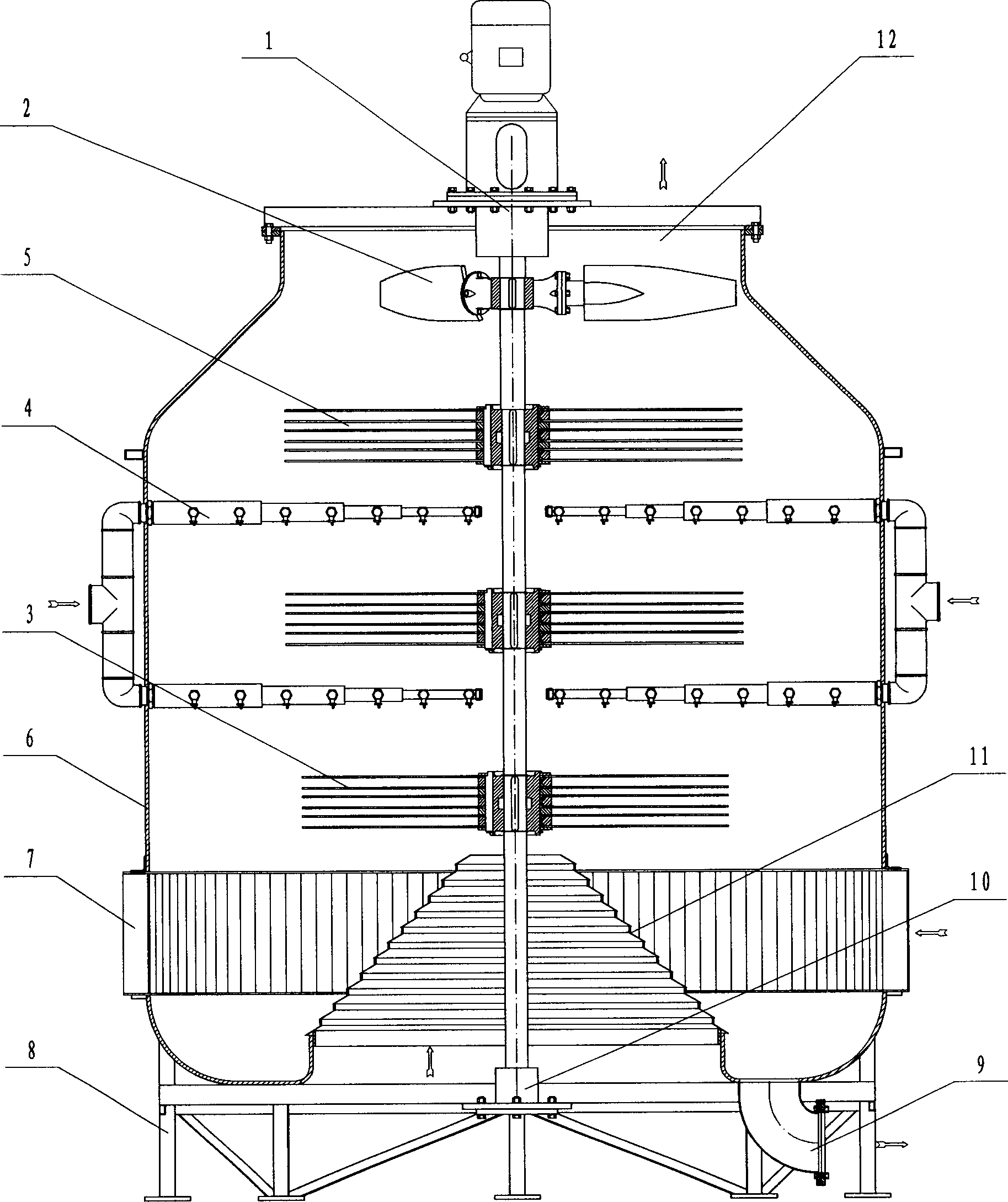
[0070] see figure 1 , the present embodiment is a single-axis driven single-guided double-layer spray counter-flow swirl cooling tower designed according to the first technical solution of the present invention. for liquid cooling. It includes a tower body 6, a set of transmission device 1, a water shield 11, two dispersing pinwheels 3, a defogging pinwheel 5, two layers of liquid spraying devices 4, a draft impeller 2, and a Cover tower body 6 support 8. The tower body 6 is urn-shaped, with a section of tapered diameter reduction at the top, and a sump and drainpipe at the bottom. The transmission device 1 includes a shaft, a bearing, a bearing box, and a motor. The motor and the shaft are directly connected through a coupling.
[0071] The needle wheel is that U-shaped needle seedlings 15 are uniformly and densely arranged in a radial shape and hung on the positioning ring 16. The positioning ring 16 of the needle seedlings 15 is hung and the spacer ring 17, backing plate...
Embodiment 2
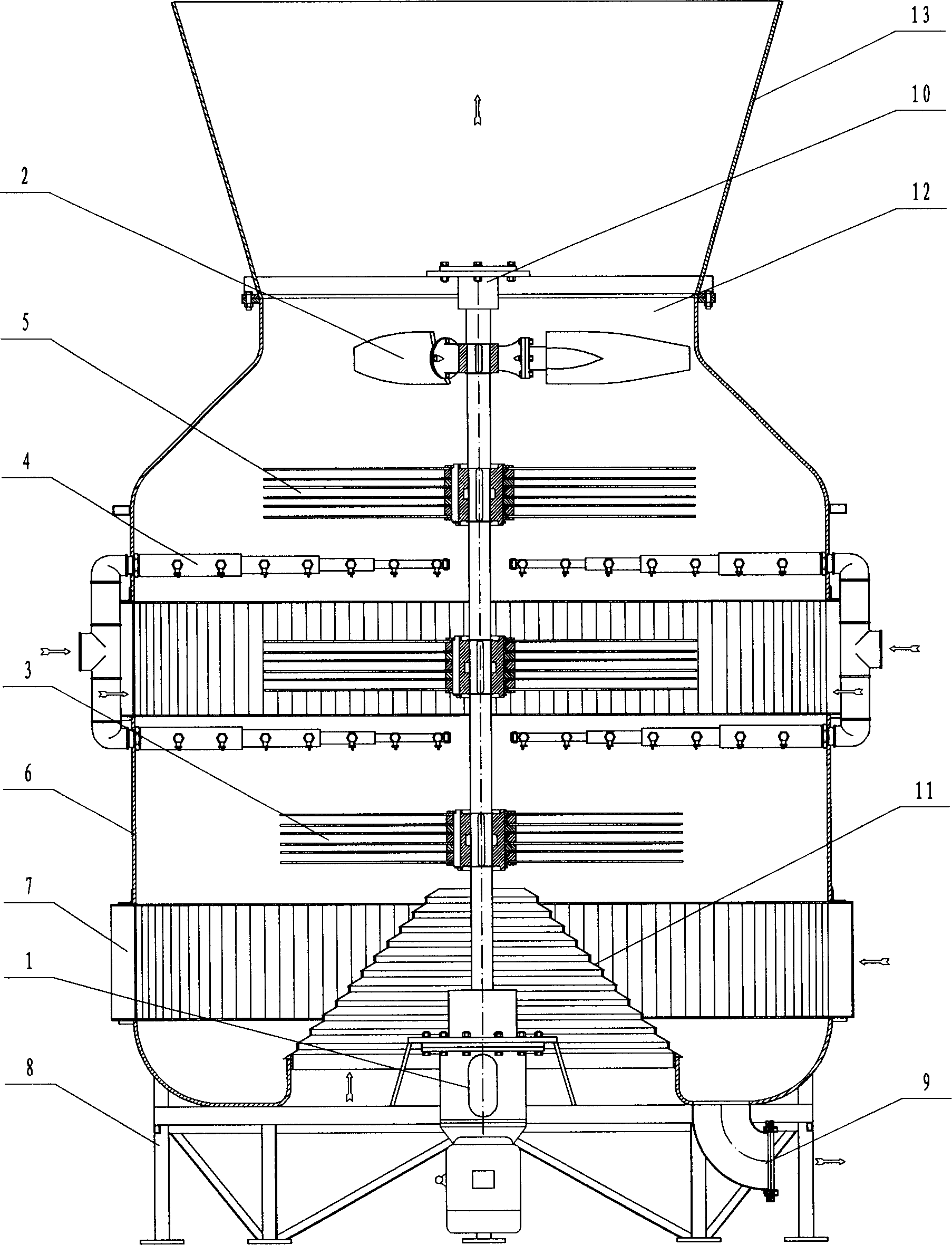
[0077] see figure 2, this embodiment is a double-layer spray counter-flow swirl cooling tower with double-guided air-guiding and double-layer spraying under the lower drive designed according to the first technical solution of the present invention, which is used for liquid cooling. It includes a tower body 6, a set of transmission device 1, a water shield 11, two dispersing pinwheels 3, a defogging pinwheel 5, two layers of liquid spraying devices 4, a draft impeller 2, a wind turbine Barrel 13. The characteristics of the five parts including the water shield 11, the dispersing pin wheel 3, the defogging pin wheel 5, the liquid spray device 4, and the fan impeller 2 are exactly the same as those in the first embodiment, except that the transmission device 1 is fixed on the tower body 6 On the bracket 8, the bearing end 10 is fixed on the upper part of the tower body 6 with a flange through a channel steel truss. At the same time, a layer of cross-flow wind deflector is adde...
Embodiment 3
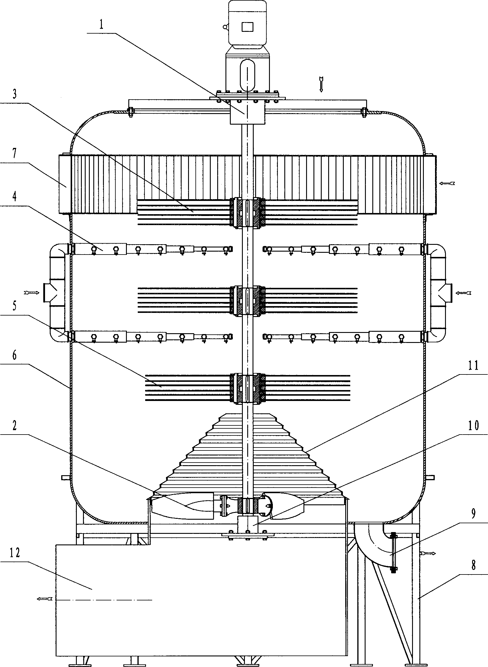
[0079] see image 3 , this embodiment is a single-shaft driven upper single-guided double-layer spray downstream swirl cooling tower designed according to the third technical solution of the present invention, which is used for liquid cooling. It includes a tower body 6, a transmission device 1, a water shield 11, a dispersing pin wheel 3, a defogging pin wheel 5, two-layer liquid spraying devices 4, and a draft impeller 2. The transmission device 1, the water shield 11, the dispersing pinwheel 3, the defogging pinwheel 5, the liquid spraying device 4, the exhaust impeller 2, and other five parts have the same characteristics as the first embodiment, except that the tower body 6 is self-contained. The upper part of the countercurrent and cross flow are mixed into the air. The tower body 6 is straight and cylindrical. wind direction.
PUM
 Abstract
Description
Claims
Application Information