

Optical fibre for wavelength division multiplexed system and manufacturing method thereof
A manufacturing method and optical fiber technology, which are applied in wavelength division multiplexing systems, electromagnetic wave transmission systems, transmission systems, etc., can solve the problems of complicated pipelines in urban systems, difficulty in laying long lengths, and no implementation, and reduce the amount of waveform distortion. , Good manufacturability, guaranteeing the effect of transmission loss
- Summary
- Abstract
- Description
- Claims
- Application Information
AI Technical Summary
Problems solved by technology
Method used
Image

Examples
no. 1 Embodiment
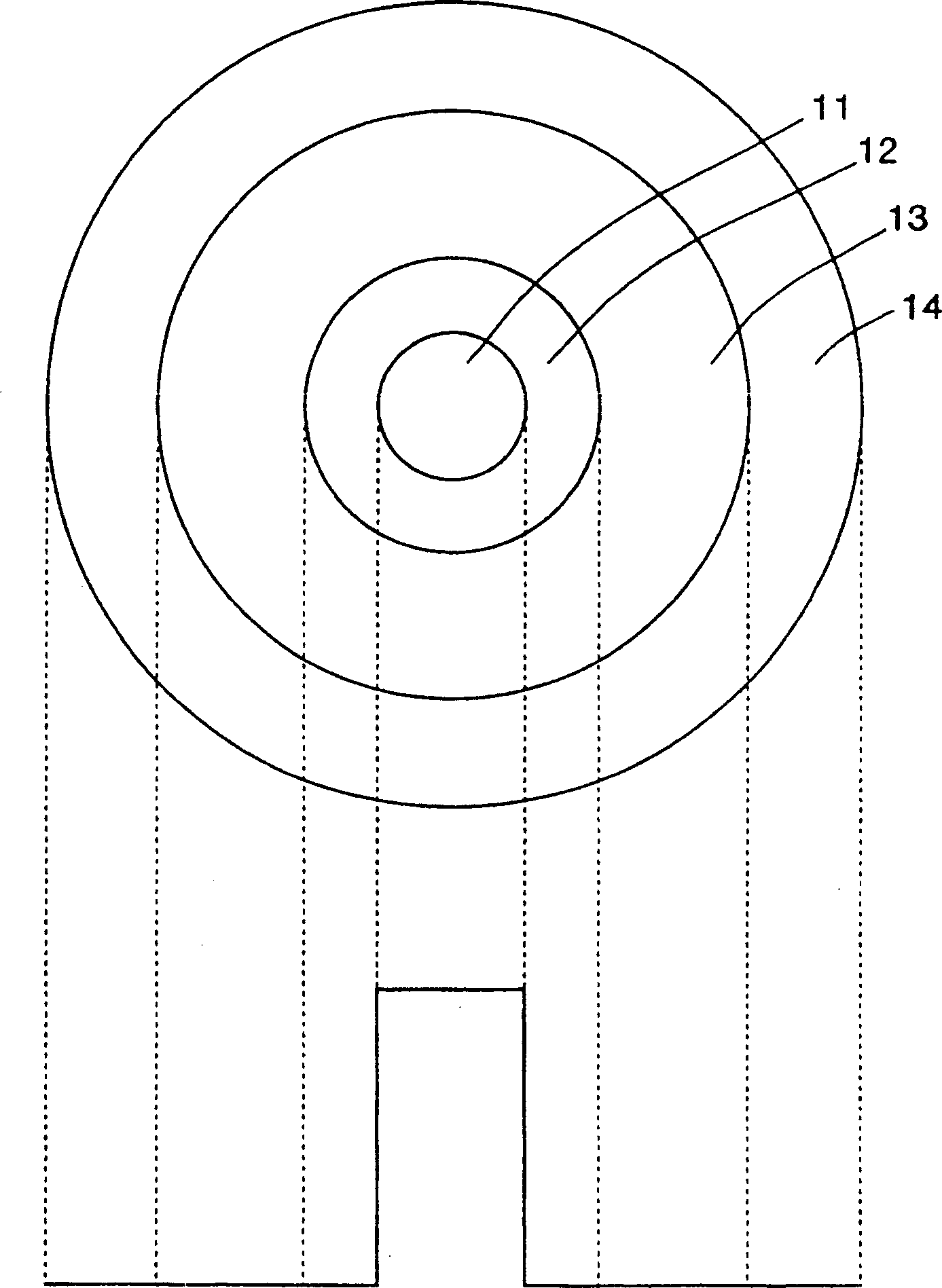
[0085] The optical fiber of the first embodiment has the Figure 4 In the refractive index distribution composed of the stepped core with a refractive index of 41 and the cladding with a refractive index of 42, the MFD at a wavelength of 1310nm is 8.5μm, the zero-scattering wavelength is 1326nm, and the dispersion slope is 0.08 in the wavelength region of 1280-1324nm ps / nm 2 / km, the absolute value of the scattering value in this wavelength region is 0.4-3.4ps / nm / km, and the cut-off wavelength is 1250nm. Therefore, A×B (product of MFD and cutoff wavelength) is 10600. Also, the average transmission loss at a wavelength of 1310 nm is 0.34 dB / km, and the average transmission loss at a wavelength of 1383 nm is 0.29 dB / km. Furthermore, when this optical fiber was subjected to a hydrogen aging test, the increase in transmission loss at a wavelength of 1383 nm before and after the test was 0.00 dB / km.
no. 2 Embodiment
[0087] The optical fiber of the second embodiment has Figure 4 The refractive index distribution shown, the MFD at the wavelength of 1310nm is 8.1μm, the zero-scattering wavelength is 1340nm, and the dispersion slope is 0.08ps / nm in the 1.3μm band 2 / km, the absolute value of the scattering value in the 1.3μm band is 1.6~5.2ps / nm / km, and the cut-off wavelength is 1100nm. Therefore, A×B (product of MFD and cutoff wavelength) is 8900. Also, the average transmission loss at a wavelength of 1310 nm is 0.34 dB / km, and the average transmission loss at a wavelength of 1383 nm is 0.29 dB / km. Furthermore, when this optical fiber was subjected to a hydrogen aging test, the increase in transmission loss at a wavelength of 1383 nm before and after the test was 0.00 dB / km.
no. 3 Embodiment
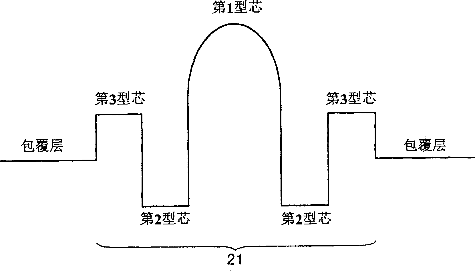
[0089] The optical fiber refractive index profile of the present invention is not limited to Figure 4 As shown, it can also be for example Figure 5 The distribution shown. The distribution is: the first type core has a peak at the center of the refractive index 51, the refractive index is only ≥1 greater than the cladding refractive index 54, the second type core has a refractive index 52 smaller than ≥2, and the third type core has a refractive index Big ≥ 3.
[0090] The optical cable of the present invention can ensure compatibility with already laid transmission lines, and provide an optical fiber for WDM that suppresses generation of four-wave mixing in the 1.3 μm band.
[0091] Furthermore, the optical fiber of the present invention is an optical fiber with good manufacturability when the MFD at a wavelength of 1310 nm is 9.5 μm or less, or when the zero-scattering wavelength is 1325 to 1350 nm, and is an optimal optical fiber.
[0092] And, the optical fiber of the...
PUM
 Abstract
Description
Claims
Application Information