Integrated branching network system and joint connector

Active Publication Date: 2006-03-23
YAZAKI CORP
View PDF11 Cites 0 Cited by
  • Summary
  • Abstract
  • Description
  • Claims
  • Application Information

AI Technical Summary

Benefits of technology

[0010] The above constituted circuits lead to reduction of

Problems solved by technology

The inventors had found out that particular branching points to which plural branch nodes are centralize

Method used


Image

  • Integrated branching network system and joint connector
  • Integrated branching network system and joint connector
  • Integrated branching network system and joint connector

Examples


Embodiment Construction

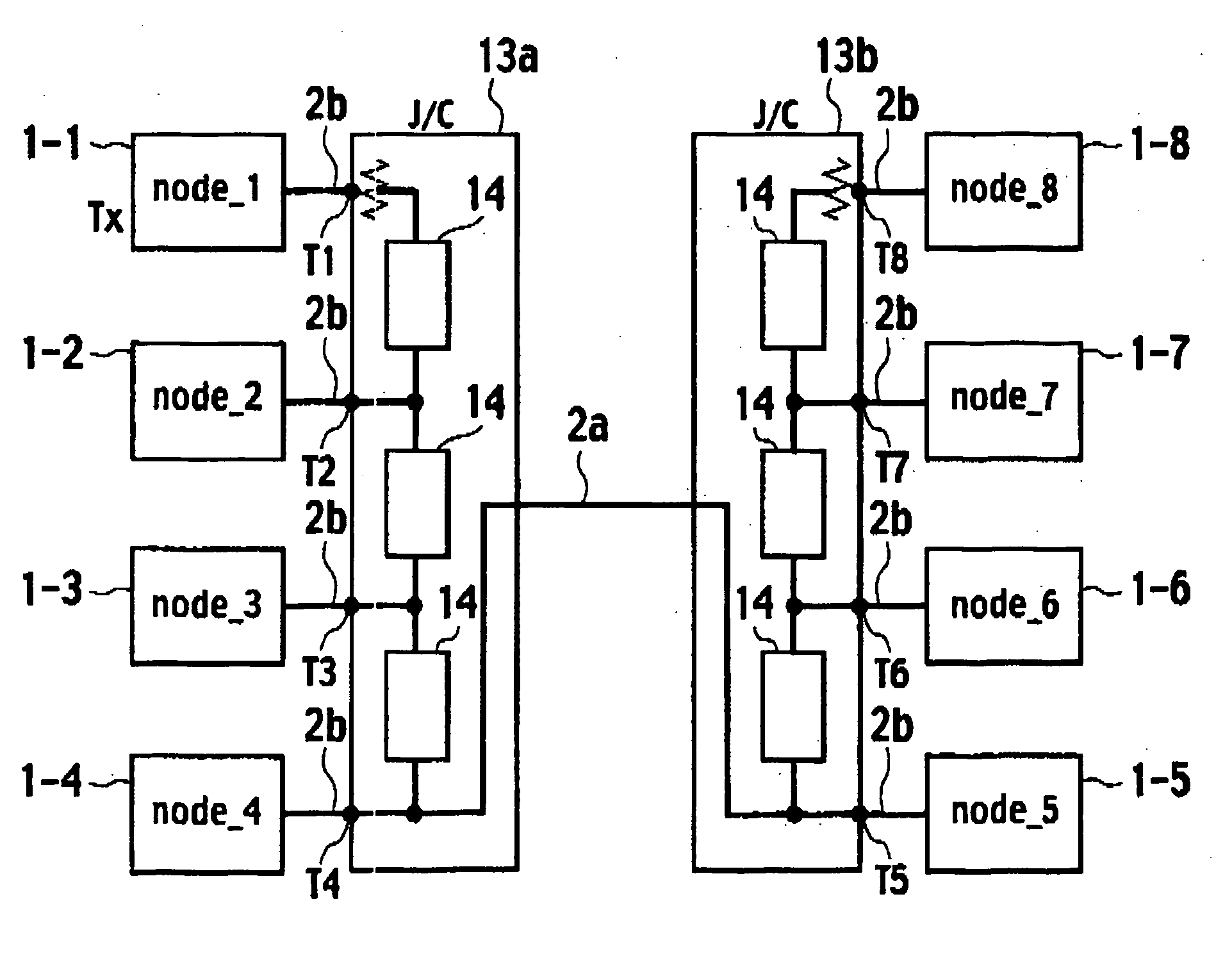
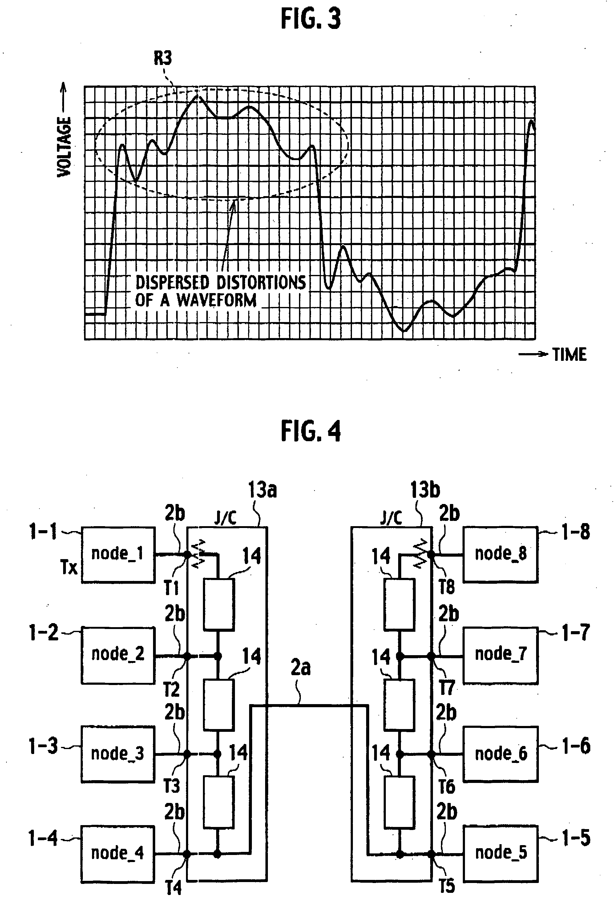
[0016] A first embodiment of the present invention will be described hereinafter with reference to FIGS. 1 to 3. A network system in accordance with the first embodiment is provided with plural nodes (eight nodes in this illustration) 1-1 to 1-8 and a communication line 2 for linking the nodes 1-1 to 1-8. These nodes are for example respective ECUs (Electronic Control Unit).

[0017] Each of the communication line 2 is provided with a main line 2a, joint connectors (J / C) 3a and 3b, and plural branch lines 2b respectively connected with the joint connectors 3a and 3b (four branch lines with each J / C). Nodes 1 are respectively connected with the branch lines 2b.

[0018] The joint connectors 3a and 3b are provided with terminals T1 to T4 and T5 to T8, which are respectively connected with the nodes 1-1 to 1-4 or 1-5 to 1-8 via the branch lines 2b. The adjacent terminals T1 to T4 and T5 to T8 are interlinked via conductors 11 (circuits having characteristic impedances). The conductors 11 a...


PUM


Abstract

A network system is provided with a joint connector for branching a communication line to plural lines respectively linked with plural nodes, the joint connector is provided with terminals for respectively linking with plural nodes, and circuits respectively having characteristic impedances, the circuits respectively linking adjacent pairs of the terminals.

Description

BACKGROUND OF THE INVENTION [0001] 1. Field of the Invention [0002] The present invention in general relates to an integrated branching network system and a joint connector used therein, and in particular relates to an art for reduction of distortions of a waveform at the joint connector. [0003] 2. Description of the Related Art [0004] Vehicles are these days equipped with network systems for communication of signals for controlling various electronic equipments. Such a network system is typically provided with a main line and a plurality of nodes and branching points linking the nodes with the main line. Japanese Patent Application Laid-open No. 2000-151153 discloses an art of the network system. In these network systems, distortions of waveforms of data signals are investigated in certain cases and often cause occurrence of data errors. SUMMARY OF THE INVENTION [0005] The inventors had found out that particular branching points to which plural branch nodes are centralized and conn...

Claims


Application Information

Patent Timeline
IPC IPC(8): H04L12/56H04L12/40H01R13/6474H01R13/66H01R31/08H03H7/48H04B3/02
CPCG05B2219/21123H04L25/0278G06F13/4086
Inventor FUJIHIRA, KATSUYAAOSHIMA, SAYAKA
Owner YAZAKI CORP
Why Eureka
Try Eureka