Method for measuring transformation ratio of transformer in power failure state

A technology of current transformers and voltage transformers, which is applied in the field of measuring and calculating the transformation ratio of transformers in the state of power failure, and in the field of measuring and calculating the transformation ratio of transformers in the state of power failure, which can solve the problems of small transformer induced voltage, potential safety hazards of using mains power, and large sampling errors and other problems to achieve the effect of increasing the input voltage amplitude, stabilizing the measured voltage value, and reducing waveform distortion

Inactive Publication Date: 2012-08-01
SUQIAN POWER SUPPLY COMPANY OF JIANGSU PROVINCE POWER +1
View PDF2 Cites 4 Cited by
  • Summary
  • Abstract
  • Description
  • Claims
  • Application Information

AI Technical Summary

Problems solved by technology

These two methods have certain disadvantages: the up-current method is not conducive to the convenience of on-site work, and the cost is high, and it is difficult to achieve up-current under high current; Large measurement errors and poor security
[0004] 1. On-site work still requires an external power supply and the required equipment is still relatively heavy. In the case of a power outage, a backup power supply must be prepared for testing, and there are hidden dangers in safety when using mains power.
[0005] 2. When the voltage method is used to measure the transformation ratio of the current transformer, the primary coil is open, the magnetic density of the iron core is very high, and it is easy to be saturated, which will cause harm to the transformer and affect the measurement error
[0006] 3. Large and small transformation ratios are not easy to measure accurately, because the input voltage is very small under the premise of ensuring that there is no magnetic saturation, the induced voltage of the large transformation ratio transformer will be very small, and the sampling error will be relatively large

Method used


Image

  • Method for measuring transformation ratio of transformer in power failure state
  • Method for measuring transformation ratio of transformer in power failure state
  • Method for measuring transformation ratio of transformer in power failure state

Examples


Embodiment Construction

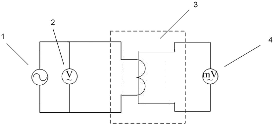
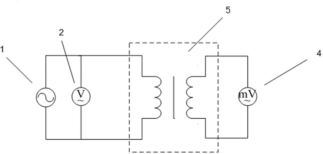
[0031] Refer to attached Figure 1~4 , a method for measuring and calculating the transformation ratio of a transformer in a power failure state, including testing two kinds of transformers, a current transformer and a voltage transformer;

[0032] When measuring current transformers, the following steps are included:

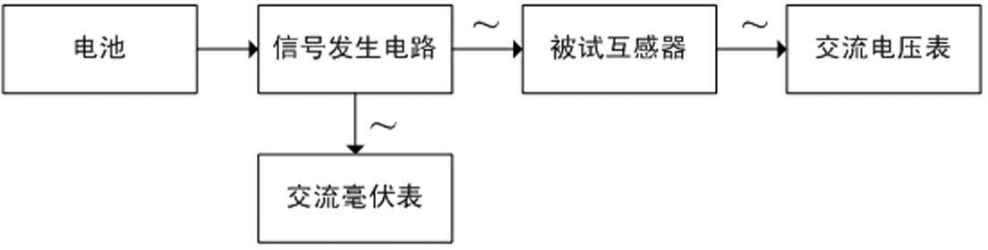
[0033] 1) The signal generating circuit 1 is powered by a power supply, the output terminal of the signal generating circuit 1 is connected to the secondary side of the current transformer 3 and the second sampling display element 2, and the primary side of the current transformer 3 is connected to the first sampling display element 4 connected;

[0034] 2) The primary and secondary sides of the current transformer 3 read the voltage value through the first sampling display element 4 and the second sampling display element 2 at the same time, and the voltage value is calculated by the single-chip computer after manual calculation or sampling. the transformati...


PUM


Abstract

The invention relates to a transformation ratio measuring method, in particular to a method for measuring the transformation ratio of a transformer in a power failure state and belongs to the technical field of electrical measurement. The method which is applicable to a current transformer and a voltage transformer comprises the following steps that: 1) an output end of a signal generation circuit, the transformer and a second sampling display element are connected, and the transformer is connected with a first sampling display element; 2) the transformer reads a voltage value through the first sampling display element and the second sampling display element; and 3) if a singlechip calculates the transformation ratio of the transformer in the step 2), the singlechip outputs a calculated result to a display screen. The method for measuring the transformation ratio of the transformer in the power failure state is reasonable in design, simple in structure and diversified in form. By combination of the method and the singlechip, a special instrument is manufactured. The method is a reliable auxiliary method for checking the transformation ratio for metering and relay protection in the power industry.

Description

technical field [0001] The invention relates to a method for measuring and calculating the transformation ratio of a transformer in a power failure state, and relates to a method for measuring and calculating the transformation ratio of a transformer, in particular to a method for measuring and calculating the transformation ratio of a transformer in a power failure state, and belongs to the technical field of electrical measurement. Background technique [0002] The transformer is an extremely important electric energy metering device, and the accuracy of its transformation ratio is directly related to the fairness and justice of electric energy metering. It is very necessary to measure and calculate the transformation ratio on site (that is, to focus on the turns ratio without considering the ratio angle difference of the transformer), and it is an essential and important work for many positions in the power system. At present, there are several methods for measuring the t...

Claims


Application Information

Patent Timeline
Patent Type & Authority Applications(China)
IPC IPC(8): G01R29/20
Inventor 李华
Owner SUQIAN POWER SUPPLY COMPANY OF JIANGSU PROVINCE POWER
Why Eureka
Try Eureka