Ultrasonic wave partial discharge sensor designed with high-precision signal frequency reduction circuit

A circuit design, high-precision technology, applied in testing circuits, testing dielectric strength, testing using acoustic measurements, etc., can solve the problems of large external interference of signal frequency reduction, increased device cost, and inability to detect small signals, reducing The effect of small waveform distortion and voltage loss, stable network resonance point, and good detection effect

Active Publication Date: 2019-11-08
GUANGZHOU POWER SUPPLY BUREAU GUANGDONG POWER GRID CO LTD
View PDF12 Cites 1 Cited by
  • Summary
  • Abstract
  • Description
  • Claims
  • Application Information

AI Technical Summary

Problems solved by technology

However, in the prior art, the detection effect of the detection circuit is poor, and it is prone to inertial distortion, negative peak cutting distortion, and noise will be introduced at the same time; the series diode envelope detection is suitable for large signal peak detection, and cannot detect small signals. It is necessary to add active components such as operational amplifiers, which have high requirements for operational amplifiers and increase the cost of the device; the traditional filter circuit has a small dynamic response range and cannot handle both small and large signals; the traditional passive filter circuit is amplified in the passband The multiple and its cutoff frequency vary with the load, which is not suitable for occasions with high signal processing requirements. At the same time, the passband of traditional filters is also affected by the input resistance and output resistance, that is, the internal resistance of the input signal source will make The resonance point of the filter network is shifted, thereby reducing the filtering effect; the overall signal down-frequency is greatly affected by external interference, which makes the sensitivity of the detection device low

Method used


Image

  • Ultrasonic wave partial discharge sensor designed with high-precision signal frequency reduction circuit
  • Ultrasonic wave partial discharge sensor designed with high-precision signal frequency reduction circuit
  • Ultrasonic wave partial discharge sensor designed with high-precision signal frequency reduction circuit

Examples


Embodiment Construction

[0028] The following will clearly and completely describe the technical solutions in the embodiments of the present invention with reference to the accompanying drawings in the embodiments of the present invention. Obviously, the described embodiments are only some, not all, embodiments of the present invention. Based on the embodiments of the present invention, all other embodiments obtained by persons of ordinary skill in the art without making creative efforts belong to the protection scope of the present invention.

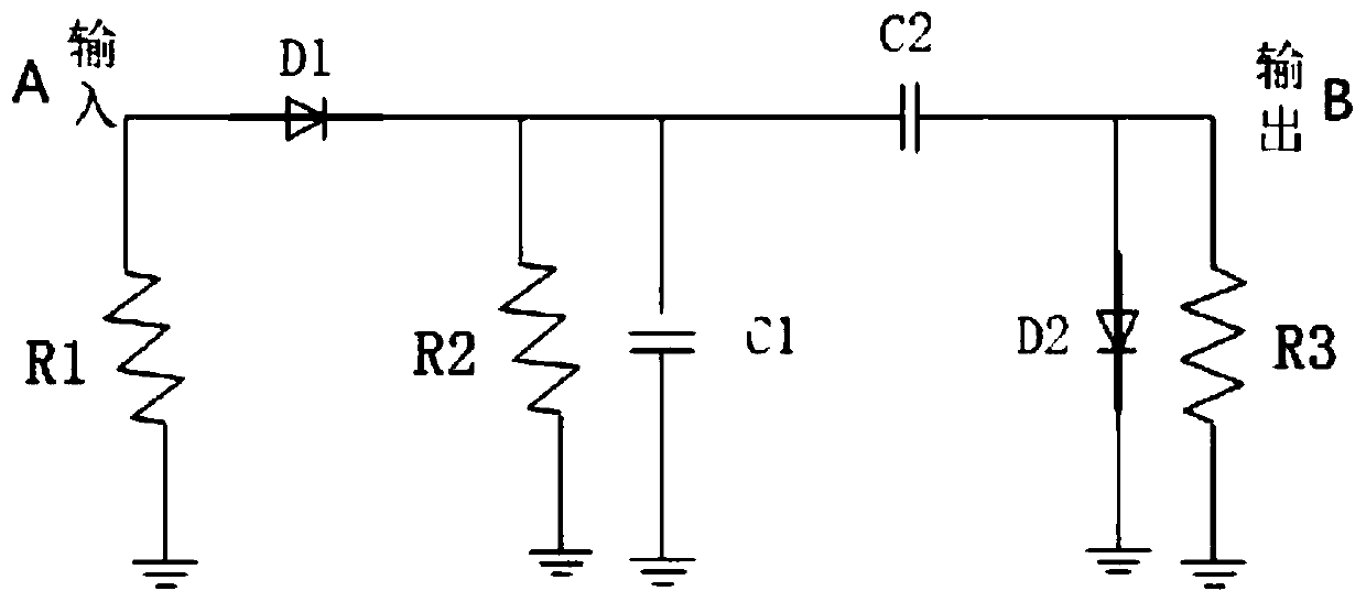
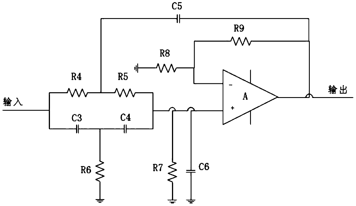
[0029] The purpose of the present invention is to provide an ultrasonic partial discharge sensor designed with a high-precision signal frequency reduction circuit, which has a high-precision dedicated signal frequency reduction circuit, a simple circuit structure, and both small and large signal processing, which can greatly improve partial discharge. detection accuracy and detection sensitivity.

[0030] In order to make the above objects, features and advant...


PUM


Abstract

The invention discloses an ultrasonic wave partial discharge sensor designed with a high-precision signal frequency reduction circuit. The sensor comprises the high-precision signal frequency reduction circuit, and the high-precision signal frequency reduction circuit comprises a wave detection circuit and a wave filter circuit which are electrically connected with each other; the wave detection circuit comprises a first resistor R1, a second resistor R2, a third resistor R3, a first diode D1, a second diode D2, a first capacitor C1 and a second capacitor C2; the wave filter circuit comprisesa fourth resistor R4, a fifth resistor R5, a sixth resistor R6, a seventh resistor R7, an eighth resistor R8, a ninth resistor R9, a third capacitor C3, a fourth capacitor C4, a fifth capacitor C5 andan operational amplifier A. The ultrasonic wave partial discharge sensor designed with the high-precision signal frequency reduction circuit has the high-precision special signal frequency reductioncircuit, the structure of the circuit is simple, processing of small signals and large signals is integrated, and the detection precision and detection sensitivity of partial discharge can be greatlyimproved.

Description

technical field [0001] The invention relates to the technical field of circuit design of an ultrasonic partial discharge sensor, in particular to an ultrasonic partial discharge sensor designed with a high-precision signal frequency reduction circuit. Background technique [0002] At present, there are a large number of low-voltage switchgears in power plants and substations, the operating environment is harsh, and the internal components are prone to aging, which leads to partial discharge. Partial discharge refers to the discharge that occurs between the electrodes but does not penetrate the two electrodes. It is due to defects in the insulation of the equipment or defects caused in the production process, and repeated breakdown and extinction occur under the action of high electric field strength. [0003] The ability of this kind of discharge is very small, so its short-term existence does not affect the insulation strength of electrical equipment, but if electrical equi...

Claims


Application Information

Patent Timeline
Patent Type & Authority Applications(China)
IPC IPC(8): G01R31/12G01R31/14
CPCG01R31/1209G01R31/14
Inventor 郝方舟赵洪山牛灿
Owner GUANGZHOU POWER SUPPLY BUREAU GUANGDONG POWER GRID CO LTD
Why Eureka
Try Eureka