A fiber optic hydrophone light emitting device based on multi-wavelength optical pulse peak staggered amplification

A technology of optical fiber hydrophone and optical fiber amplifier, applied in the field of optical processing, can solve the problem of low duty cycle, difficulty in meeting high power, high signal-to-noise ratio long-distance transmission nonlinear noise suppression, gain saturation linear and nonlinear noise surge and other issues to achieve the effect of improving performance

Active Publication Date: 2020-09-18
NAT UNIV OF DEFENSE TECH
View PDF5 Cites 0 Cited by
  • Summary
  • Abstract
  • Description
  • Claims
  • Application Information

AI Technical Summary

Problems solved by technology

Compared with the optical communication system, when the multi-wavelength analog optical pulse signal with the characteristics of wide pulse width and low duty cycle is amplified by a high-power optical amplifier, problems such as gain saturation linearity and nonlinear noise surge are more likely to occur
[0009] To sum up, although the current optical fiber hydrophone light transmitting device scheme can realize multi-wavelength and low duty cycle multiplexed optical pulse output, it is difficult to simultaneously meet the requirements of high power, high signal-to-noise ratio and long-distance transmission nonlinear noise suppression. Require

Method used


Image

  • A fiber optic hydrophone light emitting device based on multi-wavelength optical pulse peak staggered amplification
  • A fiber optic hydrophone light emitting device based on multi-wavelength optical pulse peak staggered amplification
  • A fiber optic hydrophone light emitting device based on multi-wavelength optical pulse peak staggered amplification

Examples


Embodiment Construction

[0049] In order to make the purpose, technical solutions and advantages of the present disclosure clearer, the present invention will be further described in detail below in conjunction with specific embodiments and according to the accompanying drawings. It should be noted that, in the drawings or descriptions in the specification, the content not described and some English abbreviations are the content well known to those of ordinary skill in the art. Some specific parameters given in this embodiment are only for demonstration, and the values ​​may be correspondingly changed to appropriate values ​​in different real-time manners.

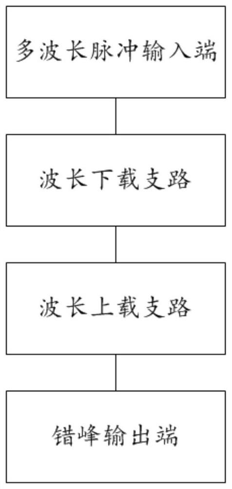
[0050] Such as figure 1 A multi-wavelength optical pulse peak stagger output component shown includes a multi-wavelength pulse input end, a wavelength download branch, a wavelength upload branch and a peak stagger output end. Among them, the multi-wavelength pulse input end is used to input the multi-wavelength optical pulse to the multi-waveleng...


PUM


Abstract

The invention provides an optical fiber hydrophone light emitting device based on multi-wavelength optical pulse peak shifting amplification, and the device comprises a multi-wavelength pulse input end which is used for inputting multi-wavelength optical pulses; a wavelength downloading branch which is connected with the multi-wavelength pulse input end through a connecting optical fiber and is used for sequentially delaying downloading of optical pulses with various wavelengths in the multi-wavelength optical pulses; a wavelength uploading branch which is connected with the wavelength downloading branch through a connecting optical fiber and is used for sequentially uploading optical pulses with various wavelengths, which are downloaded in a delayed manner, in the multi-wavelength optical pulses and combining the optical pulses into multi-wavelength quasi-continuous light; and a peak shifting output end which is connected with the wavelength uploading branch through a connecting optical fiber and is used for outputting the multi-wavelength quasi-continuous light. Low-duty-ratio optical pulses output by the multi-wavelength simultaneous section are sequentially delayed to the unoccupied time period of the pulse period in a wavelength division mode, high-power low-noise multi-wavelength optical amplification can be achieved through the high-power erbium-doped optical fiber amplifier, and the nonlinear noise suppression function is achieved. The method is applied to the technical field of optical processing.

Description

technical field [0001] The invention relates to the field of optical processing technology, in particular to a multi-wavelength optical pulse peak shift output component and an optical fiber hydrophone light emitting device based on multi-wavelength optical pulse peak shift amplification. Background technique [0002] Optical fiber hydrophone is a new generation of underwater acoustic sensor with optical fiber as the signal sensing and transmission medium. It can detect ocean acoustic field information with high sensitivity, and realize target detection and ocean acoustic field environment monitoring through complex underwater acoustic signal processing. Compared with the traditional piezoelectric detector system, the interference fiber optic hydrophone has the advantages of high sensitivity, strong anti-electromagnetic interference, large dynamic range, small size, light weight and good adaptability. More importantly, combined with the existing optical fiber communication t...

Claims


Application Information

Patent Timeline
Patent Type & Authority Patents(China)
IPC IPC(8): H04B10/50H04B10/508H04B13/02H04J14/02
CPCH04B10/506H04B10/508H04B13/02H04J14/0202
Inventor 曹春燕胡正良徐攀陈伟熊水东姚琼陈虎候庆凯王付印
Owner NAT UNIV OF DEFENSE TECH
Why Eureka
Try Eureka