Light source of light-field uniform and boundary contour clear based on light-emitting diode

A boundary, uniform technology, used in lighting devices, medical lighting, using diaphragms/collimators, etc., can solve the problem of short rated life of halogen projection lamps, and achieve simplified mechanical design, no downtime, and long service life. Effect

Inactive Publication Date: 2004-08-04
GENERAL ELECTRIC CO
View PDF0 Cites 3 Cited by
  • Summary
  • Abstract
  • Description
  • Claims
  • Application Information

AI Technical Summary

Problems solved by technology

However, due to the inherent trade-off between light output and filament life, halogen projection lamps are rated for a short life, typically a few hundred hours
This presents a disadvantage in collimator applications, where lamp replacement involves precise optical alignment of the lamp and requires a skilled service engineer or technician to perform the task
With frequent luminaire changes, this can lead to unscheduled downtime and unplanned labor costs

Method used


Image

  • Light source of light-field uniform and boundary contour clear based on light-emitting diode
  • Light source of light-field uniform and boundary contour clear based on light-emitting diode
  • Light source of light-field uniform and boundary contour clear based on light-emitting diode

Examples


Embodiment Construction

[0047] A first aspect of the invention proposes a light source with bright illumination, uniform light field and sharp border contrast. In order for the diaphragm to have a sharp border contrast at a given distance from the light source, the size of the light source should be small.

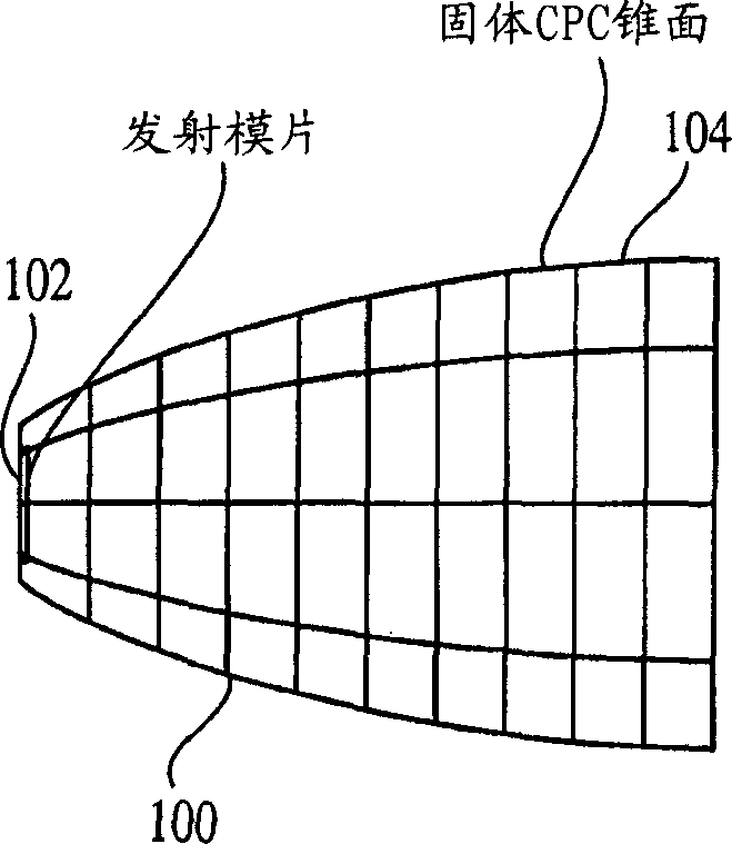
[0048] There are various optical designs to confine the LED beam to the desired cone angle. figure 1A first light emitting device 100 according to the invention is shown. The device 100 includes an LED 102 for generating a light beam; and an aperture 104 for focusing the light beam for bright illumination, uniform light field, and sharp border contrast. In the case of device 100 , stop 104 is in the form of a compound parabolic concentrator (CPC), and CPC 104 is located directly above die 102 . The left and right ends of the light collector (contractor) have circular openings, the radius (R1) of the opening at the left end is 1.5mm, and the radius (R2) of the opening at the right end is 4.5mm. ...


PUM


Abstract

An LED light device (100, 150, 170) comprising an LED (102, 152, 172) for generating a light beam, and a reflector (104, 154, 174) that concentrates the light beam to have bright illumination, uniform light field, and sharp edge contrast. The LED light device may be used in an X-ray collimator (204) to facilitate positioning a patient (206) and an X-ray machine (200) relative to each other so that an X-ray beam (212) is directed along a defined axis (214) and onto a specified target zone (220) on the patient (206). The collimator (204) comprises at least one high energy LED array (202) for generating a light beam and directing the light beam along the defined axis (214), wherein the light beam expands outward from the LED array at a beam cone angle, and an optical concentrator (104, 154, 174) having a reflective surface, wherein the light beam is emitted from the LED array at a beam cone angle defined by the reflective surface of the optical concentrator.

Description

technical field [0001] The present invention relates to a light emitting diode (LED) based light source and a system using such a light source. More specifically, the present invention relates to a light emitting diode-based light source, and systems or devices using such a light source, that provides a uniform light field with well-defined, high-contrast boundaries. Background technique [0002] There is a wide demand for light sources that provide uniform light fields with well-defined boundaries. For example, such light sources may be used in automotive or laboratory equipment applications, or in any other application requiring a uniform light field with well-defined boundaries. As another example, these light sources may be used in various medical systems, such as those that generate or use invisible electromagnetic radiation or particle beams. [0003] Today, medical systems using invisible electromagnetic radiation or particle beams are widely used in diagnosis and t...

Claims


Application Information

Patent Timeline
Patent Type & Authority Applications(China)
IPC IPC(8): G21K1/02A61B6/00A61B6/08A61N5/10G21K5/00G21K5/02H01L33/00H01L33/08H01L33/58H01L33/60
CPCF21W2131/205A61B6/08
Inventor 朱比萨·D·斯特瓦诺维克弗兰克·J·J·米勒迪特马·K·森德曼吴平凡
Owner GENERAL ELECTRIC CO
Why Eureka
Try Eureka