
System and method for simulation of nonlinear dynamic systems applicable within soft computing
A non-linear and equational technology, applied in the field of stochastic simulation, can solve problems such as increasing simulation time complexity and increasing computing resources
- Summary
- Abstract
- Description
- Claims
- Application Information
AI Technical Summary
Problems solved by technology
Method used
Image

Examples
Embodiment Construction
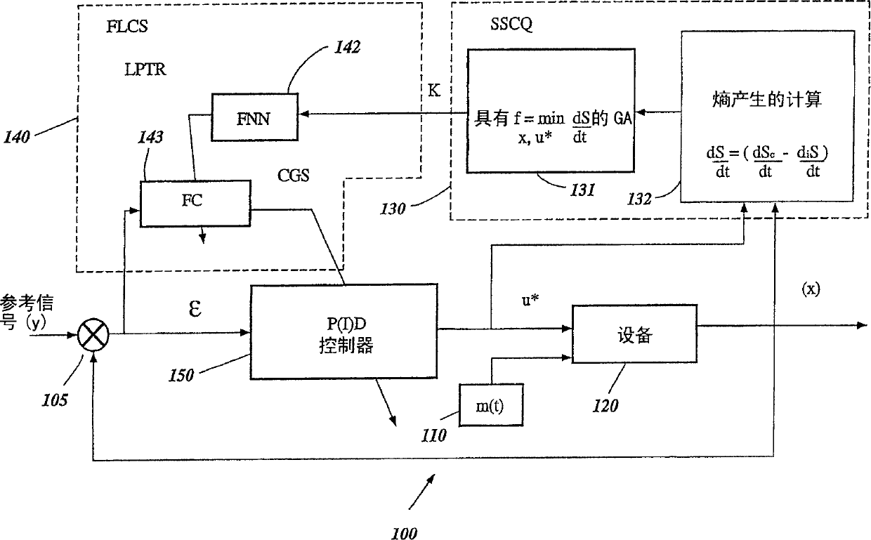
[0030] figure 1 A block diagram of a control system 100 for controlling equipment based on soft computing is shown. In the controller 100, the reference signal y is provided to the first input of the adder 105. The output of the adder 105 is an error signal ε, which is provided to the input of the fuzzy controller (FC) 143 and the input of the proportional-integral-derivative (PID) controller 150. The output of the PID controller 150 is the control signal u * , It is provided to the control input of the device 120 and the first input of the entropy calculation module 132. The interference m(t) 110 is also provided to the input of the device 120. One output of the device 120 is the response x, which is provided to the second input of the entropy calculation module 132 and the second input of the adder 105. The second input of the adder 105 is inverted so that the output of the adder 105 (error signal ε) is the value of the first input minus the value of the second input.
[0031]...
PUM
 Abstract
Description
Claims
Application Information