Device for producing filaments from thermoplastic synthetic

A synthetic, thermoplastic technology for applications such as filament/thread forming, nonwovens, textiles, and papermaking, which can solve problems such as not producing satisfactory results

Active Publication Date: 2006-04-12
REIFENHAEUSER GMBH& CO KG MASCHFAB
View PDF0 Cites 11 Cited by
  • Summary
  • Abstract
  • Description
  • Claims
  • Application Information

AI Technical Summary

Problems solved by technology

However, these measures have not yielded satisfactory results

Method used


Image

  • Device for producing filaments from thermoplastic synthetic

Examples


Embodiment Construction

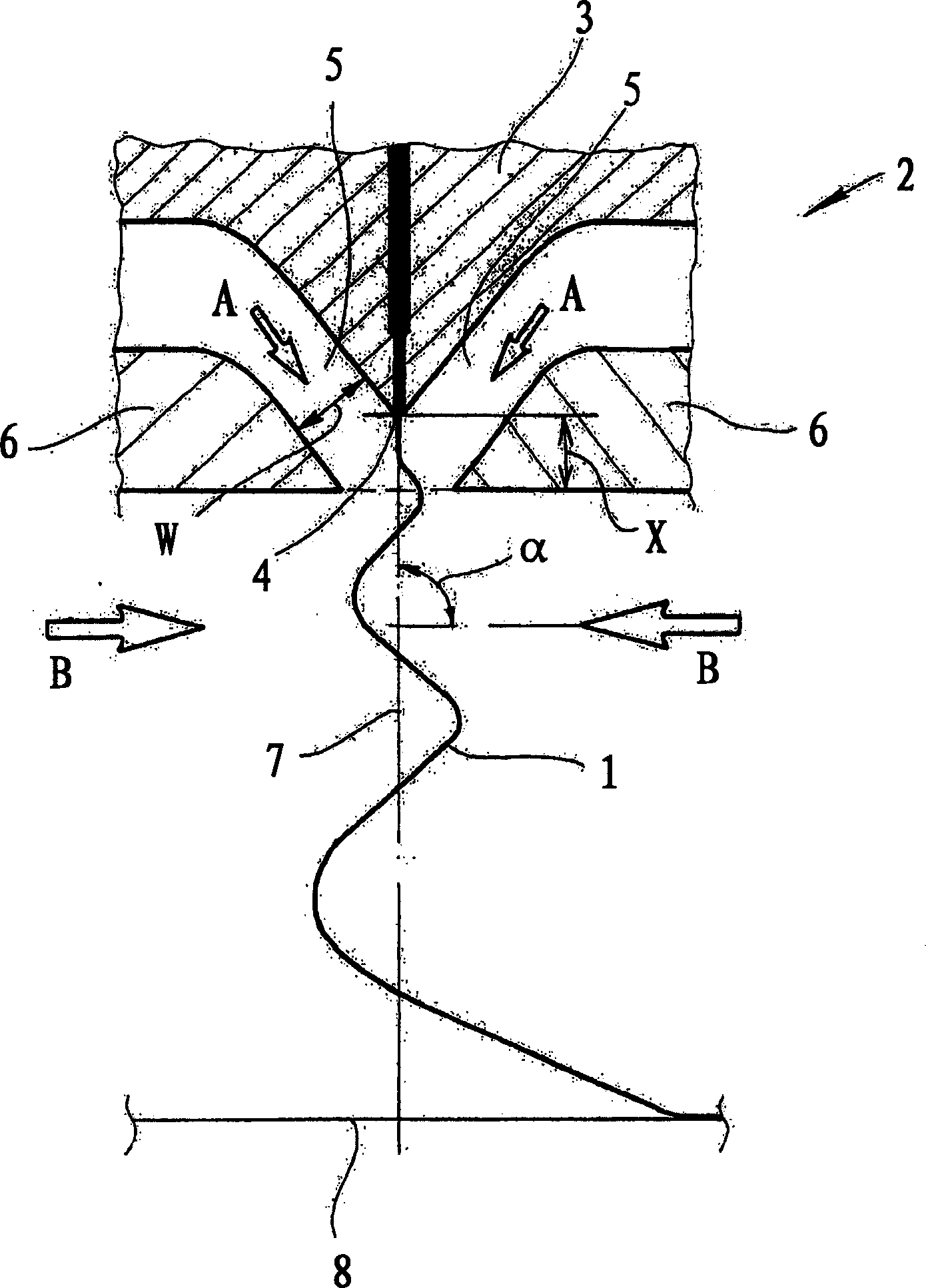
[0019] An apparatus for manufacturing filaments 1 from thermoplastic composites is shown. The apparatus has a melt blown die 2. The meltblowing die 2 is equipped with a composite guide core 3, which in the present embodiment as an example has a row of nozzles 4 to discharge the molten composite. This row of nozzles 4 extends perpendicular to the horizontal plane of the paper.

[0020] There are supply devices (not specifically shown) on both sides of the composite guide core 3, with this device, the filament 1 near the hole of the nozzle 4 can receive the first jet of air on both sides. In the example of this embodiment, the received first spray air on both sides is represented by two arrows A. It can be seen from the figure that the first jet of air and the surface jets of the first jet of air form an acute angle to each other under the nozzle 4. The first jet air is fed through the gap 5 between the composite guide core 3 and the die lip 6 on both sides. Advantageously, the die ...


PUM


Abstract

The melt blowing head (2) has a core (3) feeding molten plastic to a row of nozzle bores (4). On each side of the core, primary air is blown against the sides of the filaments, close to the nozzle openings. At least one secondary blowing-air supply is provided. This impinges on the filaments (1) from the sides, below the blowing head. Primary air is supplied on both sides through gaps (5) between the core and nozzle lips (6). Gap width (w) and spacing (x) between core tip and a notional horizontal extension (broken line) of the nozzle lips, is adjustable. The secondary air blast is introduced preferably at 75[deg]-90[deg] with respect to the axis (7) through the nozzle bore (4). It is introduced at 90[deg]. It is heated above room temperature, to preferably 60[deg]C or more. Its relative humidity is preferably less than 20%. It is blown from both sides against the filaments. Blowing from at least one side is constant. Blowing from at least one side is pulsed. A unit (8) is provided, onto which the filaments are laid, to form a spun-bonded fleece fabric.

Description

Technical field [0001] The present invention relates to an apparatus for manufacturing filaments from a thermoplastic composition, which has a meltblowing die with a composite guide core, the core having at least one row of nozzles for discharging the molten composite, the The die head also has a supply device which is arranged on both sides of the composite guide core for the first jet of air. With this device, the filaments near the nozzle hole can receive the first jet of air on both sides . Within the scope of the present invention, the equipment according to the present invention is used to produce endless filaments. In addition, within the scope of the present invention, the above-mentioned filaments are also deposited on a deposition device to form a nonwoven web or meltblown fiber web. Preferably, the meltblown fiber web manufactured in this way is used as a filter or in a filter. Background technique [0002] There are various variations in practice of the type of equipm...

Claims


Application Information

Patent Timeline
Patent Type & Authority Applications(China)
IPC IPC(8): D01D4/02D01D5/08D01D5/098D04H3/00
CPCD01D4/025D01D5/098D04H3/02D01D4/00
Inventor 德特勒夫·弗赖汉斯-格奥尔格·戈伊斯米夏埃尔·拉廷斯基
Owner REIFENHAEUSER GMBH& CO KG MASCHFAB
Why Eureka
Try Eureka