

Method for avoiding dew point corrosion of heat pipe heat exchanger and a heat pipe heat exchanger
A heat pipe heat exchanger and dew point corrosion technology, applied in the air heat pipe heat exchanger and flue gas field, can solve the problems of reduced waste heat recovery economy, increased heat exchange area, increased investment, etc., and achieves the effect of simple structure
- Summary
- Abstract
- Description
- Claims
- Application Information
AI Technical Summary
Problems solved by technology
Method used
Image

Examples
Embodiment 1
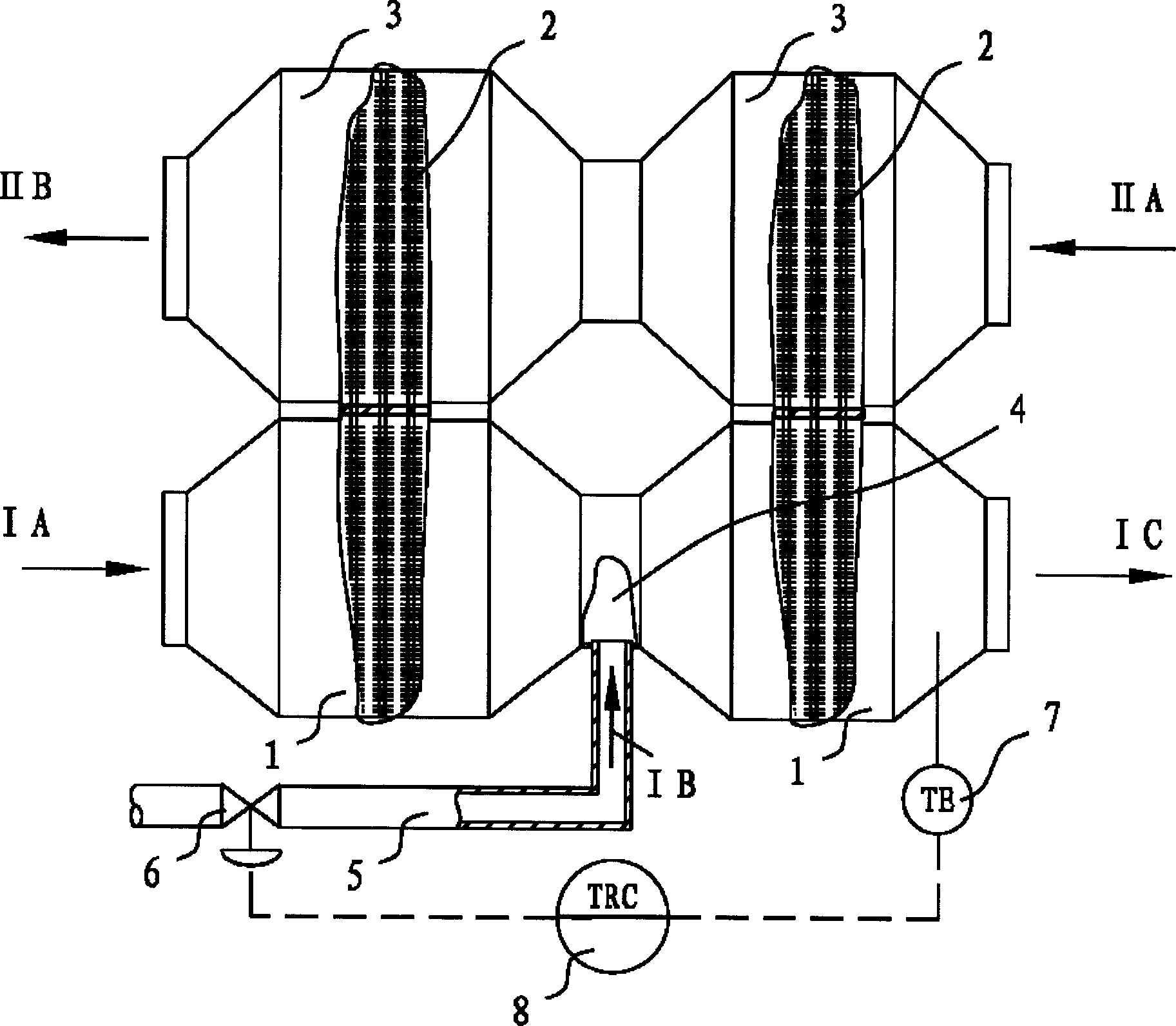
[0022] See attached figure 1 , the heat pipe heat exchanger includes a flue gas channel 1, a heat pipe group 2 and a heated air channel 3, the flue gas channel and the heated air channel are parallel to each other, the heating section of the heat pipe group is in the flue gas channel, and the heat dissipation section is in the heated air channel channel. There is a high-temperature flue gas inlet 4 located in two equal parts of the flue gas passage, and a flow control valve 6 is located in the passage 5 for passing the high-temperature flue gas. A temperature measuring element 7 is arranged at the outlet of the flue gas channel, and the temperature measuring element is connected to the flow control valve through the controller 8 through the signal transmission line.
[0023] The flue gas and the heated air pass through the flue gas channel and the heated air channel in opposite directions respectively. The high-temperature flue gas enters the flue gas channel in the direction...
Embodiment 2
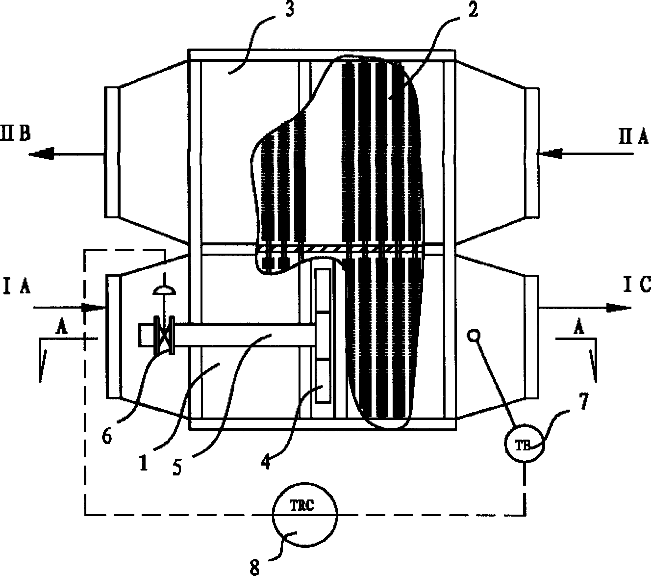
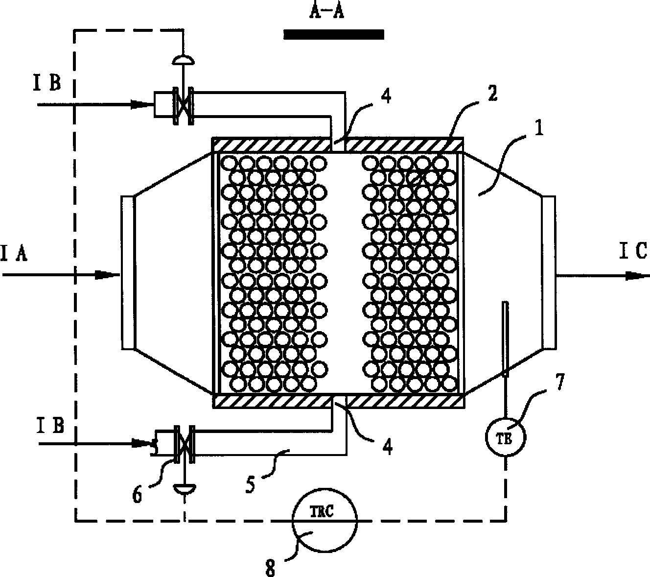
[0025] See figure 2 and image 3 , the heat pipe heat exchanger includes a flue gas channel 1, a heat pipe group 2 and a heated air channel 3, and the flue gas channel and the heated air channel are juxtaposed with each other. The heating section of the heat pipe group is in the flue gas passage, and the heat dissipation section is in the heated air passage. There is a high-temperature flue gas inlet 4 on the two side walls of the two equal parts of the flue gas passage, and a flow control valve 6 is located in the passage 5 for passing the high-temperature flue gas. A temperature measuring element 7 is arranged at the outlet of the flue gas channel, and the temperature measuring element is connected to the flow control valve through the controller 8 through the signal transmission line.
[0026] The flue gas and the heated air pass through the flue gas channel and the heated air channel in opposite directions respectively. The high-temperature flue gas enters the flue gas ...
Embodiment 3
[0028] See Figure 4 and Figure 5, the heat pipe heat exchanger includes a flue gas channel 1, a heat pipe group 2 and a heated air channel 3, and the flue gas channel and the heated air channel are juxtaposed with each other. The heating section of the heat pipe group is in the flue gas passage, and the heat dissipation section is in the heated air passage. There is a high-temperature flue gas inlet 4 on the bottom wall at two equal parts of the flue gas passage. In order to better distribute the incoming high-temperature flue gas in the flue gas passage, the inlet 4 is designed as a long and narrow horizontal shape. The inlet of the high-temperature flue gas is directly placed at the entrance of the flue gas passage 1, which makes the structure of the whole heat pipe heat exchanger more concise. There is a flow control valve 6 in the channel 5 for passing the high-temperature flue gas, and a temperature measuring element 7 is installed at the outlet of the flue gas channe...
PUM
 Abstract
Description
Claims
Application Information